Network Enhancers - "Delivering Beyond Boundaries" Headline Animator

Showing posts with label Virtual Switching. Show all posts

Monday, March 4, 2013

Cisco virtual router targets the cloud


The Cisco CSR 1000V router is designed for enterprise network managers who want to have a little piece of their Cisco infrastructure in the cloud.

The Cisco CSR 1000V router is designed for enterprise network managers who want to have a little piece of their Cisco infrastructure in the cloud.

Whether that's for firewalling, VPN or dynamic routing the CSR 1000V supports all major technologies in IOS -- the idea is that a virtual router gives the network manager the flexibility to enforce policy, connect or provide high availability using familiar Cisco tools and technologies.

We tested the CSR 1000V, a full-featured IOS XE router running v3.8S of XE in a VMware-compatible virtual machine. Does it work? Yes, in fact, it works just fine. It works great, actually.
In our functional testing, the CSR 1000V met all the requirements we'd expect for this type of environment. We tried bringing up VPN connections, defining firewall and NAT rules, and running both OSPF and BGP routing protocols. We set up two CSR 1000V virtual machines on two different hosts, and used HSRP to failover between them. We exercised both IPv4 and IPv6, and we tested management with Cisco's ever-popular command line, as well as SNMP monitoring and remote SYSLOG logging.

With thousands of pages of IOS documentation, we may not have scratched the surface of full functional testing, but certainly the key features that we think most enterprise network managers will want are all in place and working just fine.

The version of the CSR 1000V we tested is only supported on VMware's ESXi 5 infrastructure. We looked at an early release version; Cisco told us that the virtual appliance should be available to all customers around March. At that time, IOS XE will be upgraded to v3.9. Cisco is also predicting that it will support Amazon Web Services (based on Citrix's XenServer hypervisor technology) and Red Hat KVM with the v3.10 release of the CSR 1000V in July. Microsoft's Hyper-V isn't on Cisco's public road map, at least not yet.

Running the CSR 1000V is not for the faint of heart. We started out with the idea that we'd put it on our test VMware farm, which was running older servers with vSphere v4. In years of testing, that's never given anyone a problem until Cisco came along.

The CSR 1000V not only requires vSphere v5, but also has very strict hardware requirements, including a minimum of four physical (not virtual, but physical) cores, all in the same socket, dedicated to the CSR 1000V without any sharing, 4GB of memory, and Intel Nehalem or newer CPUs. Don't follow the specifications, and you've got a crashing CSR 1000V, which isn't much fun.
Cisco told us that it is considering allowing future versions of the CSR 1000V to share CPUs with other virtual machines, but the version we tested doesn't have that option: Four CPU cores had to be exclusively dedicated to the CSR 1000V.

Compared to alternative software router technologies, the CSR 1000V is fairly heavyweight. The requirement for so many physical cores and the newer CPUs may limit the options for deploying CSR 1000V in clouds running older hardware or ones without quad-core CPUs.

Performance

We looked at performance on the CSR 1000V and found that it meets its requirements, but they're pretty modest. Cisco technical staff told us that they've gotten up to 1Gbps out of the CSR 1000V, but the official data sheet cuts that number considerably, to 50Mbps. Cisco told us to expect higher throughput (in the 1Gbps range, depending on hardware, of course) in future versions later in 2013.

Cisco may be shooting low here for some reason, but we think that network managers might be disappointed with this level of performance in cloud deployments. After all, one of the reasons for using cloud service providers is to get extra bandwidth at lower cost. The performance we saw would be fine for typical management and off-site database applications, but you wouldn't want to put the CSR 1000V in front of an Internet-facing Web server unless the bandwidth requirements were very low.

With the CSR 1000V in pure routing mode and sending and receiving packets from external devices outside of the VMware environment, we were able to push about 48Mbps through it before it started dropping packets, just about hitting that 50Mbps number. While the overall system CPU wasn't really breaking a sweat at that level, one of the four cores was flat-lined at nearly 100%. Either Cisco is wasting cycles as part of its bandwidth cap, or the virtual appliance was topped out. We confirmed this suspicion by turning on firewall and NAT features, and got the same within-data-sheet performance, although with a higher CPU load spread across more cores.

We validated that the VMware hardware we were using (a Dell R610 server) was not the problem by loading up the open source Vyatta router on the same hardware and pushing a hefty 500Mbps (input) through the hardware, using only a single CPU core and a single external Gigabit Ethernet port. We also tested the CSR 1000V and the Vyatta router on Cisco's own UCS Express hardware, with the same results.

With Cisco pushing the AppNav-XE technology into the CSR 1000V, the low throughput may inhibit adoption in Internet-facing applications.

AppNav is Cisco coming backward into the load balancer world no one wants to compete head-on with F5, not even Cisco with a coordinated technology that handles distribution of traffic from the WAN into application servers, such as instant messaging, file sharing, Web traffic and Microsoft Exchange.

AppNav is officially "complementary" to Cisco's older WCCP (Web Cache Communication Protocol), the much-maligned load distribution and redirection technology Cisco took on when it purchased ArrowPoint Communications in 2000. But many network managers will discover that with AppNav they can do away with ugly and complicated WCCP deployments.

We successfully built a small AppNav deployment, putting the CSR 1000V in front of two other virtual machines running Web services and found it easy to put together with ample documentation but we didn't stress AppNav's configuration capabilities or try and scale up because of the 50Mbps limit on the CSR 1000V.

Licensing

For years, IOS users have gotten away with simple and non-intrusive licensing models from Cisco. The CSR 1000V tries to keep a fairly lightweight licensing model, but there's no question that Cisco is not giving this virtual hardware away. Starting with the March release, you'll be able to license the appliance on a term basis. This means that you have to buy a one-, three- or five-year license, and when that license expires, the CSR 1000V throttles traffic down to 2.5Mbps.

To lock down the CSR 1000V virtual machine as much as possible, Cisco has built a licensing scheme that requires a different license for each virtual machine. Although you can vMotion the CSR 1000V all over your network without requiring a new license, you can't just clone a legal CSR 1000V to get a second CSR 1000V appliance -- you must pay for and apply a different license to the cloned VM.

Network managers looking for high availability can either use the built-in high-availability features of VMware to resurrect a single CSR 1000V, if the host hardware fails, or can use Cisco's own HSRP to keep two (or more) legally licensed CSR 1000Vs alive all the time. Or both.

Overall, Cisco has come to a reasonable approach to keep its intellectual property intact. And network managers intent on using the CSR 1000V for their CCIE study labs shouldn't fear, as the CSR 1000V has a 60-day evaluation mode that doesn't require a license.
 

Friday, February 8, 2013

Cisco unveils open networking "fabric" for data centers, clouds


Network speed, latency, and greater network port density in a single unit are key considerations for customers deploying virtualized data centers and moving to a managed cloud environment where microseconds count, and physical data center real estate is limited.


To sustain their differentiation, Cisco today unveiled the Cisco Nexus 6000, the world’s first 96-port, line rate 40-gigabit fixed form factor switch with Ethernet and Fiber Channel over Ethernet (FCoE) and 1-microsecond latency across all ports. For example, the Nexus 6000 can transfer the entire content of the Library of Congress in just 210 seconds.

Cisco also added rich services modules to its Nexus 7000 Series, and 40-gigabit uplink extensions to its Nexus 5000 and 2000 product lines. With these extensions, Cisco’s Unified Fabric portfolio now delivers an unequaled end-to-end 40-gigabit solution providing design flexibility for virtual and cloud deployments of converged networks with 10G and 40G FCoE support, while enabling greater visibility in the network.

The Nexus 6000 Series expands Cisco’s data center switching portfolio, providing greater deployment flexibility through higher density and scalability. The new Nexus 6000 Series brings the highest 10GE/40GE density in a fixed form factor, and offers unprecedented network visibility and programmability. It runs the industry-leading Cisco NX-OS with robust integrated layer 2 and 3 feature set.

The Cisco Nexus 7000 Series Network Analysis Module (NAM). Cisco’s flagship data center switch continues to evolve into a services-rich platform with the announcement of the first services blade, the Network Analysis Module. The NAM brings application awareness and performance analytics to the Cisco Nexus 7000, empowering IT with unparalleled actionable visibility into the network, improving application performance, optimizing network resources and helping to more effectively manage services delivery in cloud and virtualized deployments.

Cisco Nexus 2248PQ fabric extender and the Nexus 5500 Series switch 40 gigabit Ethernet uplink capabilities provide investment protection and choices for an end-to-end 40GE solution. The new Nexus 5500 40GE module provides customer with the option of deploying 40GE uplinks in their existing Nexus 5500 to reduce over-subscription, while the new Nexus 2248PQ switch provides a 10GE top-of-rack fabric extender with 40GE uplinks.

The Nexus 1000V InterCloud orchestrates hybrid cloud environments by extending corporate enterprise environments into the provider cloud with simplicity and industry-leading security. The Nexus 1000V InterCloud preserves existing networking capabilities and L4-7 services while bringing manageability of the enterprise into the provider cloud to create a consistent, reliable, predictable environment for physical, virtual and cloud workloads, freeing IT management to run and move applications without compromise. The solution provides choice of provider clouds and operates in a hypervisor-agnostic manner.

The Cisco Virtual Network Management Center (VNMC) InterCloud offers new capabilities including a single policy point for network services across both enterprise and provider domains; the ability to manage virtual machine lifecycle across multiple hypervisors in hybrid clouds; and the ability to manage multiple provider clouds via APIs.
 

Thursday, January 24, 2013

VMware vCloud Director 5.1 New Features For Staters


For starters, just check out some of the increases in the scalability:
 
 
Supported in 5.0
Supported in VCD 5.1 (*)
# of VMs
20,000
30,000
# of powered on VMs
10,000
10,000
# VMs per vApp
64
128
# of hosts
2,000
2,000
# of VCs
25
25
# of users
10,000
10,000
# of Orgs
10,000
10,000
Max # vApps per org
500
3,000
# of vDCs
10,000
10,000
# of Datastores
1,024
1,024
# of consoles
300
500
# of vApp Networks
-
1,000
# of External Networks
-
512
# of Isolated vDC Networks
-
2,000
# of Direct vDC Networks
-
10,000
# of Routed vDC Networks
-
2,000
# Network Pools
-
25
# Catalogs
1,000
10,000
 
(Note: The numbers represented here are ‘soft’ numbers and do not reflect hard limits that can not be exceeded)
You’ll notice that there are some line items here that refer to ‘vDC Networks’. This is a new construct in 5.1, which replaces the organization network concept in previous versions. Organization vDC networks simplify the virtual network topology present in vCloud Director and facilitate more efficient use of resources.
 
That’s not all the networking changes present though! Major enhancements have been introduced with the Edge Gateway. Some highlights include:
 
- The ability to have two different deployment models (compact and full) to provide users a choice over resource consumption and performance.
 
- High availability provided by having a secondary Edge Gateway that can seamlessly take over in the event of a failure of the primary
 
- Multiple interfaces. In previous versions the vShield Edge device supported 2 interfaces. The Edge Gateways in vCloud Director 5.1 now support 10 interfaces and can be connected to multiple external networks.
 
The networking services that are provided out of the box with vCloud Director 5.1 have also been enhanced. DHCP can be provided on isolated networks. NAT services now allow for the specification of SNAT and DNAT rules to provide a finer degree of control. There’s also support for a virtual load balancer that can direct network traffic to a pool of servers using one of several algorithms.
 
Additionally, vCloud Director 5.1 introduces support for VXLAN. This provides ‘virtual wires’ that the cloud administrator can use to define thousands of networks that can be consumed on demand.
 
Providing the ability to have a L2 domain with VXLAN that encompasses multiple clusters gives rise to the need to support the use of multiple clusters within a Provider VDC. This is part of the Elastic VDC feature that has now been extended to support the Allocation Pool resource model, along with the Pay-As-You-Go model.
 
Support for Storage Profiles provides the ability for cloud administrators to quickly provide multiple tiers of storage to the organizations. Previously, to do this, one had to define multiple Provider VDCs. For those who have done this, a feature has also been added to allow for the merger of multiple Provider VDCs into a single object.
 
Numerous changes were also added to increase the usability. Top on this list is the support for snapshots! The UI has also been updated to make it a easier for the end user to create new vApps, reset leases, and find items within the catalog. Support for tagging objects with metadata information is also provided through the UI as well.
 
I’m sure you’ll agree that this represents a lot of features… And I haven’t even gotten into the API extensibility features
or the support for Single Sign-On (SSO)! For now, if you want more information, I’d suggest reading the What’s New whitepaper here:


Tuesday, November 27, 2012

VXLAN Deep Dive

Courtesy - definethecloud.com
 
By far the most popular virtualization technique in the data center is VXLAN. This has as much to do with Cisco and VMware backing the technology as the tech itself. That being said VXLAN is targeted specifically at the data center and is one of many similar solutions such as: NVGRE and STT.) VXLAN’s goal is allowing dynamic large scale isolated virtual L2 networks to be created for virtualized and multi-tenant environments. It does this by encapsulating frames in VXLAN packets. The standard for VXLAN is under the scope of the IETF NVO3 working group.
 
image
 
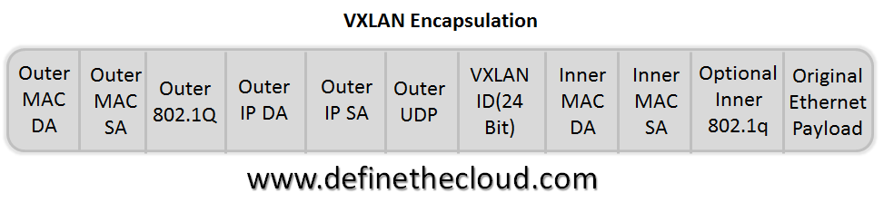
The VXLAN encapsulation method is IP based and provides for a virtual L2 network. With VXLAN the full Ethernet Frame (with the exception of the Frame Check Sequence: FCS) is carried as the payload of a UDP packet. VXLAN utilizes a 24-bit VXLAN header, shown in the diagram, to identify virtual networks. This header provides for up to 16 million virtual L2 networks.
 
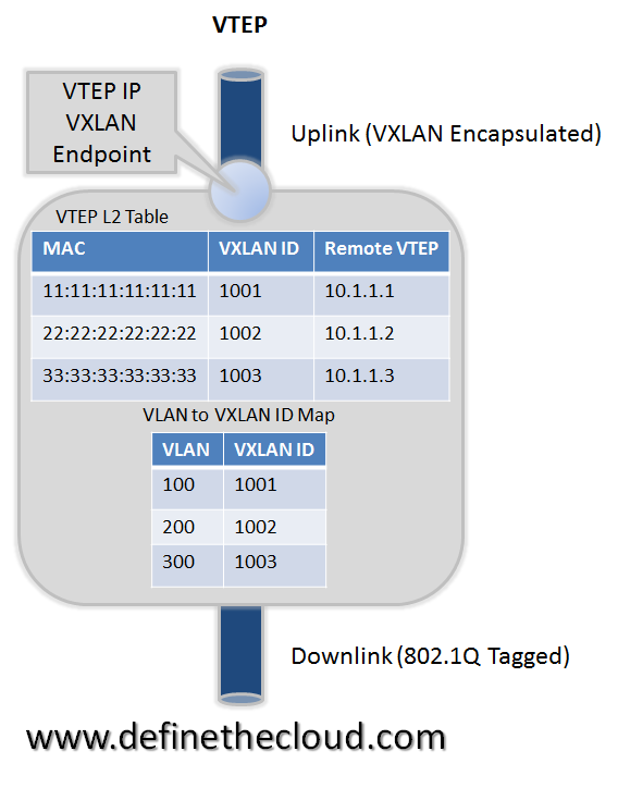
Frame encapsulation is done by an entity known as a VXLAN Tunnel Endpoint (VTEP.) A VTEP has two logical interfaces: an uplink and a downlink. The uplink is responsible for receiving VXLAN frames and acts as a tunnel endpoint with an IP address used for routing VXLAN encapsulated frames. These IP addresses are infrastructure addresses and are separate from the tenant IP addressing for the nodes using the VXLAN fabric. VTEP functionality can be implemented in software such as a virtual switch or in the form a physical switch.
 
VXLAN frames are sent to the IP address assigned to the destination VTEP; this IP is placed in the Outer IP DA. The IP of the VTEP sending the frame resides in the Outer IP SA. Packets received on the uplink are mapped from the VXLAN ID to a VLAN and the Ethernet frame payload is sent as an 802.1Q Ethernet frame on the downlink. During this process the inner MAC SA and VXLAN ID is learned in a local table. Packets received on the downlink are mapped to a VXLAN ID using the VLAN of the frame. A lookup is then performed within the VTEP L2 table using the VXLAN ID and destination MAC; this lookup provides the IP address of the destination VTEP. The frame is then encapsulated and sent out the uplink interface.
 
 
image
Using the diagram above for reference a frame entering the downlink on VLAN 100 with a destination MAC of 11:11:11:11:11:11 will be encapsulated in a VXLAN packet with an outer destination address of 10.1.1.1. The outer source address will be the IP of this VTEP (not shown) and the VXLAN ID will be 1001.
 
In a traditional L2 switch a behavior known as flood and learn is used for unknown destinations (i.e. a MAC not stored in the MAC table. This means that if there is a miss when looking up the MAC the frame is flooded out all ports except the one on which it was received. When a response is sent the MAC is then learned and written to the table. The next frame for the same MAC will not incur a miss because the table will reflect the port it exists on. VXLAN preserves this behavior over an IP network using IP multicast groups.
 
Each VXLAN ID has an assigned IP multicast group to use for traffic flooding (the same multicast group can be shared across VXLAN IDs.) When a frame is received on the downlink bound for an unknown destination it is encapsulated using the IP of the assigned multicast group as the Outer DA; it’s then sent out the uplink. Any VTEP with nodes on that VXLAN ID will have joined the multicast group and therefore receive the frame. This maintains the traditional Ethernet flood and learn behavior.
 
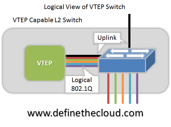
VTEPs are designed to be implemented as a logical device on an L2 switch. The L2 switch connects to the VTEP via a logical 802.1Q VLAN trunk. This trunk contains an VXLAN infrastructure VLAN in addition to the production VLANs. The infrastructure VLAN is used to carry VXLAN encapsulated traffic to the VXLAN fabric. The only member interfaces of this VLAN will be VTEP’s logical connection to the bridge itself and the uplink to the VXLAN fabric. This interface is the ‘uplink’ described above, while the logical 802.1Q trunk is the downlink.
 
image
 
Summary of part I:
 
VXLAN is a network overlay technology design for data center networks. It provides massively increased scalability over VLAN IDs alone while allowing for L2 adjacency over L3 networks. The VXLAN VTEP can be implemented in both virtual and physical switches allowing the virtual network to map to physical resources and network services. VXLAN currently has both wide support and hardware adoption in switching ASICS and hardware NICs, as well as virtualization software.
 
 
Part - II
 
This part will dive deeper into how VXLAN operates on the network.
 
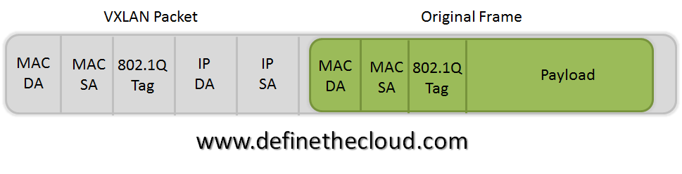
Let’s start with the basic concept that VXLAN is an encapsulation technique. Basically the Ethernet frame sent by a VXLAN connected device is encapsulated in an IP/UDP packet. The most important thing here is that it can be carried by any IP capable device. The only time added intelligence is required in a device is at the network bridges known as VXLAN Tunnel End-Points (VTEP) which perform the encapsulation/de-encapsulation. This is not to say that benefit can’t be gained by adding VXLAN functionality elsewhere, just that it’s not required.
 
image
 
Providing Ethernet Functionality on IP Networks:
 
As discussed in Part 1, the source and destination IP addresses used for VXLAN are the Source VTEP and destination VTEP. This means that the VTEP must know the destination VTEP in order to encapsulate the frame. One method for this would be a centralized controller/database. That being said VXLAN is implemented in a decentralized fashion, not requiring a controller. There are advantages and drawbacks to this. While utilizing a centralized controller would provide methods for address learning and sharing, it would also potentially increase latency, require large software driven mapping tables and add network management points. We will dig deeper into the current decentralized VXLAN deployment model.
 
VXLAN maintains backward compatibility with traditional Ethernet and therefore must maintain some key Ethernet capabilities. One of these is flooding (broadcast) and ‘Flood and Learn behavior.’ I cover some of this behavior here (http://www.definethecloud.net/data-center-101-local-area-network-switching) but the summary is that when a switch receives a frame for an unknown destination (MAC not in its table) it will flood the frame to all ports except the one on which it was received. Eventually the frame will get to the intended device and a reply will be sent by the device which will allow the switch to learn of the MACs location. When switches see source MACs that are not in their table they will ‘learn’ or add them.
 
VXLAN is encapsulating over IP and IP networks are typically designed for unicast traffic (one-to-one.) This means there is no inherent flood capability. In order to mimic flood and learn on an IP network VXLAN uses IP multi-cast. IP multi-cast provides a method for distributing a packet to a group. This IP multi-cast use can be a contentious point within VXLAN discussions because most networks aren’t designed for IP multi-cast, IP multi-cast support can be limited, and multi-cast itself can be complex dependent on implementation.
 
Within VXLAN each VXLAN segment ID will be subscribed to a multi-cast group. Multiple VXLAN segments can subscribe to the same ID, this minimizes configuration but increases unneeded network traffic. When a device attaches to a VXLAN on a VTEP that was not previously in use, the VXLAN will join the IP multi-cast group assigned to that segment and start receiving messages.
 
image
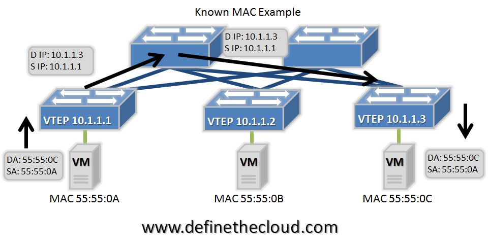
In the diagram above we see the normal operation in which the destination MAC is known and the frame is encapsulated in IP using the source and destination VTEP address. The frame is encapsulated by the source VTEP, de-encapsulated at the destination VTEP and forwarded based on bridging rules from that point. In this operation only the destination VTEP will receive the frame (with the exception of any devices in the physical path, such as the core IP switch in this example.)
 
image
 
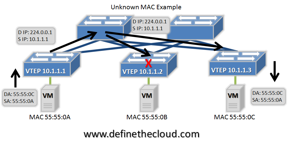
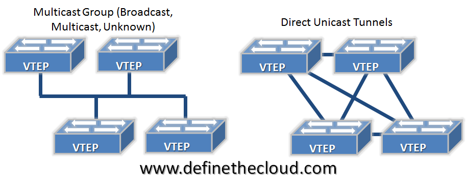
In the example above we see an unknown MAC address (the MAC to VTEP mapping does not exist in the table.) In this case the source VTEP encapsulates the original frame in an IP multi-cast packet with the destination IP of the associated multicast group. This frame will be delivered to all VTEPs participating in the group. VTEPs participating in the group will ideally only be VTEPs with connected devices attached to that VXLAN segment. Because multiple VXLAN segments can use the same IP multicast group this is not always the case. The VTEP with the connected device will de-encapsulate and forward normally, adding the mapping from the source VTEP if required. Any other VTEP that receives the packet can then learn the source VTEP/MAC mapping if required and discard it. This process will be the same for other traditionally flooded frames such as ARP, etc. The diagram below shows the logical topologies for both traffic types discussed.
 
image
 
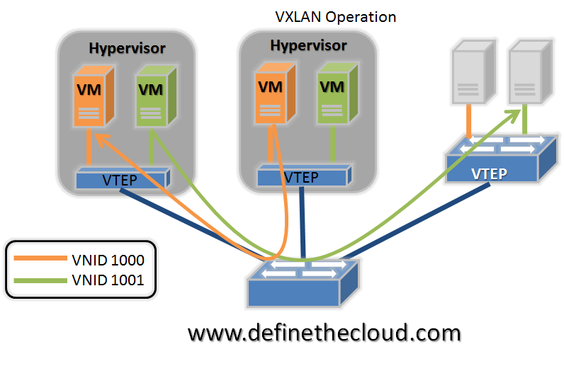
As discussed in Part 1 VTEP functionality can be placed in a traditional Ethernet bridge. This is done by placing a logical VTEP construct within the bridge hardware/software. With this in place VXLANs can bridge between virtual and physical devices. This is necessary for physical server connectivity, as well as to add network services provided by physical appliances. Putting it all together the diagram below shows physical servers communicating with virtual servers in a VXLAN environment. The blue links are traditional IP links and the switch shown at the bottom is a standard L3 switch or router. All traffic on these links is encapsulated as IP/UDP and broken out by the VTEPs.
 
image
 
Summary of Part II:
 
VXLAN provides backward compatibility with traditional VLANs by mimicking broadcast and multicast behavior through IP multicast groups. This functionality provides for decentralized learning by the VTEPs and negates the need for a VXLAN controller.

Thursday, August 30, 2012

Cisco Preps 'Arista Killer'

 
Cisco Systems Inc. (Nasdaq: CSCO) is preparing to release a top-of-rack switch that it's been touting as an Arista Networks Inc. killer, Light Reading has learned.
 
The Nexus 3500, which sources say was originally designed by the team now running Insieme Networks Inc. , is reportedly a low-latency switch built for cloud networks where virtual machines get moved around a lot. Both are factors that Arista boasts about with its own switches.
In fact, Arista is running a demo here showing off its virtual-machine capabilities. It was the subject of an Arista press release Friday.
The Nexus 3500 reportedly will be based on a Broadcom Corp. (Nasdaq: BRCM) Ethernet switching chip -- the Trident II that was announced Monday, according to one source. But sources say it's also going to include an application-specific integrated circuit (ASIC) for Layer 3 multicast -- which is necessary for a virtual machine, after it's been moved, to communicate with the rest of the network.
That ASIC was designed by the team at Insieme, Cisco's spin-in startup run by the same team that did Cisco's Nuovo and Andiamo spin-ins, sources agree. The team has been moved off that product and onto the next big thing -- possibly a super-dense 100Gbit/s switch, as Light Reading reported Friday.
Let's get virtual
That Layer 3 ASIC would be useful for a technology called virtual extensible LAN (VXLAN), developed by VMware and partners. VXLAN moves virtual machines via a Layer 3 tunnel (technically, it encapsulates the packets so that the Layer 3 network can move them around). Normal virtual-machine movement happens at Layer 2, but VXLAN is more scalable and can cross network boundaries.
VXLAN, which VMware just started shipping, is one of a few technologies being proposed for this task. Microsoft has its own version, called NVGRE.
 
Arista's VMworld demo shows VXLAN hardware virtual endpoints running inside a switch, one that's part of the 7000 family but hasn't yet been announced, says Doug Gourlay, Arista's VP of marketing.
The technologies are relatively new, so Arista is trying to grab a leader's position in supporting them. That's the purpose of this week's demo, which shows interoperability with some big-name companies including F5 Networks Inc. (Nasdaq: FFIV), Palo Alto Networks Inc. and the Isilon branch of EMC Corp. (NYSE: EMC).
As is often the case, interoperability is important for smaller players like Arista, because they're up against all-in-one offerings from the bigger names, such as Cisco and VMware Inc. (NYSE: VMW).
"This has become a game of stacks. Cisco's got a stack. VMware's got a stack. Oracle Corp. (Nasdaq: ORCL) has a stack. This is how Arista can counter that," says Zeus Kerravala, principal analyst with ZK Research . It's aligning itself with the right companies -- F5, Palo Alto. That's a Who's Who."
Lowering latency

But getting back to that Nexus thing. The 3000 line is the variety of Nexus that's built specifically for low latency, targeting markets such as financial trading. It's also one of Cisco's first product lines to dabble in the OpenFlow protocol, at least according to one engineer last fall.
Kerravala wouldn't discuss the 3500 specifically, but he did think that an ASIC-based Nexus 3000 would be a logical next step. Cisco, which tends to be ASIC-happy, has been using merchant Ethernet chips in the Nexus 3000 series.
Network World uncovered some more details about the 3500 earlier in August, finding that the switch will have low enough latency to rival InfiniBand gear. Low latency has made InfiniBand, rather than Ethernet, a favored data-center fabric protocol.
Gourlay declined to comment on the existence of a potential Arista killer at Cisco. A Cisco spokeswoman declined comment as well.
 

Wednesday, August 29, 2012

Cisco Readying New Nexus 3500 Low-Latency Switch


Details are scarce but a mid-September launch for Cisco Systems' new Nexus 3500 top-of-rack switch is in the cards, a product that will reduce latency significantly compared to its current offerings.

Cisco execs aren't denying the switch is coming, but neither are they spilling the beans. Press coverage suggests the 3500 will have port-to-port latency of 250 nanoseconds, way faster than the network giant's current 3064 and 3064-X offerings.


The same coverage also points to a new network interface card (NIC), dubbed unNIC, suggesting that the combination could be pitched as an alternative to InfiniBand. Once, briefly, a champion of InfiniBand, Cisco has for some time thrown its weight behind Ethernet technologies. Meanwhile, Intel has given InfiniBand a boost with its purchase of QLogic's business in that space.


More certainly, the 3500 will mean a leapfrog for Cisco over rival Arista Networks, which offers the 7124SX with port switching latency of around 500 nanoseconds. Meanwhile, the likes of Gnodal claim sub-150 nanosecond switching for its GS7200, and Zeptonics' ZeptoMux clocks in at around 130 nanoseconds. Also, Rockflower Networks is in design/concept stage for its RM200GX-10, claiming a less than 100 nanosecond latency.


Of course, latency isn't the only measure of a switch. Low jitter, ability to cope with microbursts, buffer analytics, precision time support, layer 3 network protocol support, and management are also factors. As is price. In the future, add to that intelligence, which Arista has a lead in, with its 7124FX, featuring an internal FPGA chip for application logic.
 

Monday, August 13, 2012

IP Technology Labs Advances Touchless LAN Virtualization with Release of the FastLane-AutoConnect™ feature


IP Technology Labs, the leading provider of LAN Virtualization and Private Cloud LAN Appliances, announces general availability of its exclusive AutoConnect feature for its FastLane Gateway appliances. AutoConnect allows IpTL FastLane appliances to automatically establish a secure Ethernet VPN without any configuration of the appliance, the router, or the network. AutoConnect works especially well in network environments where NAT, Nested-NAT, or Dynamic-IP/DHCP is present on both ends of a link.
Click here for additional AutoConnect details: http://bit.ly/NhKJXZ
“Customers have been demanding solutions which uncomplicate their initiatives,” said Scott Whittle, President of IP Technology Labs. “We are pleased to provide groundbreaking innovation with AutoConnect making networking truly easy while driving value at all levels of their operation. With viable cloud based solutions meeting the shift in IT, IpTL now provides the missing link between the user, the cloud, and success.”
As the World’s Longest Ethernet Cable™ IpTL FastLane solutions place your LAN securely anywhere in the world while integrating all your wireless and wired devices seamlessly. Using any Internet connection an enterprise can create its own virtualized, private, and secure private cloud network.
“Nightmare for the competition,” said Benoy Nair, Technical Engineer at Almasa Value Distribution. “AutoConnect makes simple work out of challenging network installations. With IpTL’s Model 70 Series Gateways and AutoConnect, we can deliver a secure and fully virtualized LAN anywhere, and there is no competitive alternative…period. IpTL understands both the technical and business requirements of our customers and only IpTL delivers on the promise of Network Communications Simplified.”
The FastLane solution of SME/enterprise Secure Ethernet Gateways enables partners to meet customer’s expectations by removing the complexity and reducing the costs for transparent multi-site network connectivity.
Contact http://iptechnologylabs.com/contact for additional information and opportunities to cooperate with IPTL.
About IP Technology Labs LLC. (http://iptechnologylabs.com)
IP Technology Labs is the worldwide designer and manufacturer of the FastLane™ IP and Ethernet network appliances and plug-and-play VPN and LAN Virtulization appliances. Solving challenges imposed by infrastructure limitations for telecommunications and information technology users; IpTL simplifies, lowers the cost, and enables the connection of network devices and services over any LAN or WAN infrastructure. With products made in the USA, IpTL offers solutions for every network.

Saturday, August 11, 2012

New Cisco Unified Computing System (UCS)


Cisco UCS: The Breakthrough In Cloud And Systems Management

Learn how Cisco is paving the way towards the consolidation of IT infrastructure through virtualization with the new Cisco Unified Computing System (UCS).


Webex Session

Saturday, August 4, 2012

Virtual Networking 101: Understanding VMware Networking

On a basic, structural level, virtual networks in VMware aren’t that different from physical networks; vSphere is designed to mimic the functions of a physical network, so a lot of the network hardware you’ll find in the real world, you’ll find virtualized in VMware. If you understand how physical networks operate, then understanding virtual networking shouldn’t be too difficult.

Before jumping into an explanation of how VMware handles virtual networking, I’ll first provide a quick refresher of the basic equipment that makes up a physical network. If you already have a firm understanding of how networking works, then you can skip the following paragraph.

To connect to a network, a computer must be network-capable, meaning that it must have a working network interface controller (NIC), also known as a network card or network adapter, installed. Like its name indicates, the NIC enables the computer to interface with a network. In most business environments, computers are usually connected to a device called a switch, which creates a local area network (LAN). A LAN is a collection of interconnected network-capable devices confined to a small area. Switches are responsible for intelligently routing this network traffic to the appropriate destination.

A virtual network is made up of all of the same hardware described above, but these objects are, obviously, virtualized. A virtual network consists of one or more virtual machines that can send data to and receive data from one another. Each virtual machine represents a single computer within the network and resides on an ESX or ESXi server.

In VMware, switches are used to establish a connection between the virtual network and the physical network. With ESX and ESXi, two different kinds of switches can be used: standard switches and distributed switches.

Standard Switches

A network standard switch, virtual switch, or vSwitch, is responsible for connecting virtual machines to a virtual network. A vSwitch works similar to a physical switch — with some limitations — and controls how virtual machines communicate with one another.

The vSwitch uses the physical NICs (pNICs) associated with the host server to connect the virtual network to the physical network. In VMware, these pNICs are also called uplink adapters. Uplink adapters use virtual objects called vmnics, or virtual network adapters, to interface with the vSwitch.
Once the vSwitch has bridged the connection between the virtual network and the physical network, the virtual machines residing on the host server can begin transferring data to, and receiving data from, all of the network-capable devices connected to the physical network. That is to say, the virtual machines are no longer limited to communicating solely across the virtual network.

VMware can create a virtual network from a vSwitch mapped to one or more uplink adapters, or mapped to no uplink adapters at all. A vSwitch that lacks an assigned pNIC is called an internal vSwitch and cannot communicate with other virtual or physical machines outside of the ESX or ESXi host. Internal vSwitches are used whenever the host must remain isolated from the external network, such as when configuring a virtual appliance.

On a more technical level, a vSwitch attaches to the VMkernel inside a host server. The vSwitch is responsible for routing network traffic to the VMkernel, the VM network, and the Service Console. The VMkernel is used to manage features like vMotion, fault tolerance, network file system (NFS), and Internet small computer system interface (iSCSI); the VM network enables virtual machines running on an ESX or ESXi host to connect to the virtual and physical network; and the Service Console is used for remote management. Only ESX uses the Service Console; in ESXi, the VMkernel instead serves as the management front-end.


To connect to a vSwitch, a virtual machine must have a virtual NIC (vNIC) mapped to it — just like how physical machines can’t connect to a network without a working network adapter. In fact, if a physical machine residing outside the virtual environment were to receive data from a vNIC associated with a virtual machine, the physical machine wouldn’t be able to tell that the information was coming from a virtualized network adapter. Like pNICs, vNICs have both a MAC address and an IP address.

Each virtual machine interfaces with the vSwitch via a port. vSwitches can consist of one or more port groups, which describe how the virtual switch should route traffic between the virtual network and the virtual machines connected to the specified ports. Administrators can use port groups to configure traffic shaping and bandwidth limitations, NIC failover, and other settings.

Distributed Switches

Distributed virtual switches, or DvSwitches, simplify the network management of multiple ESX or ESXi hosts. DvSwitches provide the same features and functions as do vSwitches, but with one major difference: while a standard virtual switch can’t be assigned to more than one host server at a time, a DvSwitch can. So, rather than create identical vSwitches for multiple hosts in a datacenter, you can instead create and associate a single DvSwitch with all the applicable ESX or ESXi servers.

Unlike vSwitches, which can be managed from the local host, due to its inherent architecture,
DvSwitches must be created and controlled through vCenter Server. A DvSwitch is made up of a control plane and an input/output (I/O) plane. The control plane resides in vCenter Server and is used to configure DvSwitches, NIC bonding, uplink adapters, and VLANs. The I/O plane, or data plane, on the other hand, is a “hidden” virtual switch built into the host server.

DvSwitches also support port groups, called distributed port groups, or dvport groups. dvport groups provide the same basic functionality as do standard port groups, but offer additional features that the latter does not. For example, administrators can define not just outbound traffic shaping, but inbound traffic shaping as well, when working with dvPort groups.

That sums up the basics of virtual networking. Virtual switches are powerful networking objects that provide even greater utility than what’s described in this article. Once you understand the fundamentals, however, the more advanced aspects of VMware networking are much easier to grasp.

Monday, July 23, 2012

Fundamentals of VXLAN


 Virtual Extensible LAN (VXLAN) delivers the scalability required for multi-tenancy isolation in the cloud. See why this joint effort from Cisco, VMWare, Citrix, and Red Hat is fast becoming the first choice of engineers around the world. Host Robb Boyd guides you through the technical differences that make VXLAN a smarter, more scalable choice in your enterprise than the traditional VLAN.


Friday, December 24, 2010

VEPA: An answer to virtual switching

B

My Blog List

Networking Domain Jobs