Network Enhancers - "Delivering Beyond Boundaries" Headline Animator

Monday, March 28, 2011

Junos OS Commit Model


The router configuration is saved using a commit model: a candidate configuration is modified as desired and then committed to the system. Once committed, the router checks the configuration for syntax errors and if no errors are found, the configuration is saved as juniper.conf.gz and activated. The former active configuration file is saved as the first rollback configuration file (juniper.conf.1.gz) and all other rollback configuration files are incremented by 1. For example, juniper.conf.1.gz is incremented to juniper.conf.2.gz, making it the second rollback configuration file. The router can have a maximum of 49 rollback configurations (1–49) saved on the system.

On the router, the active configuration file and the first three rollback files (juniper.conf.gz.1, juniper.conf.gz.2, juniper.conf.gz.3 ) are located in the /config directory. If the recommended rescue file rescue.conf.gz is saved on the system, this file should also be saved in the /config directory. The factory default files are located in the /etc/config directory.
There are two mechanisms used to propagate the configurations between Routing Engines within a router:
  • Synchronization—Propagates a configuration from one Routing Engine to a second Routing Engine within the same router chassis.
    To synchronize a router’s configurations, use the commit synchronize CLI command. If one of the Routing Engines is locked, the synchronization fails. If synchronization fails because of a locked configuration file, you can use the commit synchronize force command. This command overrides the lock and synchronizes the configuration files.
  • Distribution—Propagates a configuration across the routing plane on a multichassis router. Distribution occurs automatically. There is no user command available to control the distribution process. If a configuration is locked during a distribution of a configuration, the locked configuration does not receive the distributed configuration file, so the synchronization fails. You need to clear the lock before the configuration and resynchronize the routing planes.

Note: When you use the commit synchronize force CLI command on a multichassis platform, the forced synchronization of the configuration files does not affect the distribution of the configuration file across the routing plane. If a configuration file is locked on a router remote from the router where the command was issued, the synchronization fails on the remote router. You need to clear the lock and reissue the synchronization command.

Sunday, March 27, 2011

OSPF - IOS vs Junos

There are copule different between IOS, Junos, here are the different in OSPF part,

1, router-id in junos without using route-id cmd, the junos will automate send /32 to every are in OSPF PID.

2, stub, NSSA, both will not send out 0/0 at ABR by default.

3, External route cann't summary inside OSPF conifg in Junos.

Saturday, March 26, 2011

How to optimize Ethernet for data center networks

By Tom Nolle

Ethernet has been the LAN technology of choice for decades, so it's not surprising that the role of Ethernet in data center networks has been growing. Pressure to conserve costs, consolidate data center resources, and support new software models like SOA have all combined to create a radically new set of demands on data center Ethernet.


There is little doubt that Ethernet will ultimately meet these demands in data center networks, but there's also little doubt that both the evolution of Ethernet technology and the evolution from the older Ethernet LAN models to new models will challenge data center network plans for three years – or throughout the current refresh cycle. As this transition occurs, data center and networking teams must learn ways of optimizing Ethernet as it stands. That will mean addressing latency and packet loss through a series of strategies that range from isolating storage networks to choosing the right switches.

Data center Ethernet: Beyond basic connectivity

Data center networks have evolved from their original mission of providing connectivity between central computing systems and users. There are now three distinct missions, each with its own traffic and QoS requirements to be considered:
  • Traditional client/server or "front end" traffic, which is relatively insensitive to both latency and packet loss.
  • "Horizontal" or intra-application traffic, generated in large part by the trend toward componentized software and service-oriented architecture (SOA). This traffic requires low latency but is still somewhat tolerant of packet loss.
  • Storage traffic, created by the migration of storage protocols onto IP and Ethernet (iSCSI and FCoE). Storage traffic is sensitive to latency, but it is even more sensitive to packet loss.
That the different traffic types have different data center network QoS requirements is a challenge, but that they are also highly interdependent is perhaps a greater one. Transactions generated by the user in client/server communications activate processes that must then be linked horizontally, and these processes often access storage arrays. The performance of the application is then dependent on all of these flows in combination and on whether traffic from one competes with the others.

Addressing QoS in data center networks: Isolating storage networks

If inter-dependency is an issue, then one obvious solution is to compartmentalize the traffic on independent LANs. This may seem to waste the economies of scale that Ethernet offers in the data center, but for at least some users, it is completely practical to isolate storage networks at least while migrating them to Ethernet connections. Large data centers may achieve most of the economy-of-scale benefits even if their LANs are physically partitioned. Since storage traffic is by far the most sensitive to network performance, this can substantially reduce the difficulties of managing QoS for the three application classes.

It's important to note that VLAN partitioning will not normally achieve traffic isolation because traffic access to the inter-switch trunks and queuing management don't reflect VLAN partitions on most switching products. There is a series of standards currently being reviewed by the IEEE and IETF designed to improve enterprise control over traffic classes in Ethernet networks, but the standards and their implementation continue to evolve. They include Data Center Bridging (DCB), Priority Flow Control (PFC), Lossless Service, and Enhanced Transmission Selection (ETS). Planners should review their vendors' support of each of these standards when laying out their data centers.

Steps to address latency and packet loss for data center networks

Even without standards enhancement, there are steps that can be taken to improve latency and packet loss. They include:
  • Using the highest Ethernet speeds that can be economically justified. Latency is always reduced by increasing link and inter-switch trunk speed. Low link utilization, a result of faster connections, also reduces the risk of packet loss. Where it's not practical to up-speed all the Ethernet connections, at least ensure that storage traffic is routed on the fastest connections available.
  • Using large switches instead of layers of smaller ones. This process, often called "flattening" the network, will reduce the number of switches a given traffic flow transits between source and destination. That reduces latency and the risk of packet loss. It also reduces the jitter or variability in both parameters and so makes application performance more predictable.
  • Looking for cut-through switches that enable acceleration of the switching process as opposed to the store-and-forward approach. Store-and-forward switches wait for the entire data frame to be received before it is forwarded; whereas cut-through examines the packet header first and begins to queue it for output as it is assembled from the input interface. This reduces switch latency.
  • Taking special care with the interface cards used on servers and for storage systems. Some are designed to offload considerable processing from the host, and these will offer better and more deterministic performance.
  • Routing the most critical traffic through a minimal number of switches. That means servers and storage arrays that are normally used together should be on the same switch or, at the worst, on a directly connected switch and not a path that transits an intermediate device (some call this "routing traffic on the same switch layer" rather than up or down in the hierarchy of switches).
  • Setting switch parameters on storage ports to optimize for lowest packet loss even at the expense of delay. Packet loss can be a disaster to storage-over-Ethernet protocols.
Separating user traffic for data center networks QoS

A truly optimum data center network is not something that can evolve out of a legacy structure of interconnected headquarters Ethernet switches. In fact, the integration of the "front end" or application access portion of the data center network with the back-end storage/horizontal portion is not likely to provide optimum performance.

User traffic could be completely separated on different facilities from the storage or horizontal traffic. If you plan to integrate these traffic types, you will be forcing your network to carry traffic that is delay- and loss-insensitive along with the traffic that is sensitive. That means you either have to overbuild or wait for standards to allow the traffic types to be handled differently.

At the minimum, it is important to ensure that the interior applications like storage and SOA networking are not mingled in a traffic sense with user access. This will also help secure your data center assets. You must also be sure that discovery protocols like spanning tree used in the front-end LAN are not extended to the data center, where they can interfere with traffic management and affect the recovery of the network from faults.

Both products and standards for the data center network are evolving rapidly as applications like virtualization and cloud computing emerge. Planners should review their vendors' directions in data center switching and plan near-term network changes with the future architectures in mind.

Thursday, March 24, 2011

Implementing FCoE doesn’t mean a rip-and-replace

Implementing Fibre Channel over Ethernet (FCoE) for converged data center networks doesn’t mean users have to invest in a complete rip-and-replace … even when implementing Cisco FCoE. We met with Kash Shaikh, Cisco’s data center solutions senior manager of marketing, who explains in this video that users can start Cisco FCoE implementation in the access layer with converged network adapters at the servers, and later move toward FCoE in the core.


CCIE Preperation: Five common, easily avoided errors in Routing

The following are the most common mistakes that will be performed by the candiates who are doing CCIE Perperation-- These can  are fairly common and easily avoided or resolved.

1. Filtering redistribution
When redistributing routing, you need to filter the routes properly to avoid routing loops and route feedback. Not applying filters at all is usually a significant problem, but managing the filters in a complex and poorly summarized network is such an administrative burden that missing a route here or there is extremely common. The best way to avoid this, of course, is not to do redistribution at all. In fact, it's almost always a bad decision. Friends don't let friends do mutual redistribution.

2. Mismatched neighbor parameters in OSPF
In order to form an adjacency, OSPF routers need to have quite a few parameters in common. These include authentication, area ID, mask, hello interval, router dead interval, and so on. As a result of fat fingers, nonstandard configurations or invalid passwords, deviant parameters will quite often prevent adjacencies from forming. Although it's hard to avoid typos, it's fairly easy to use the debug command for OSPF adjacencies, which will quickly let you know if mismatched parameters are a problem. Once you know that, it's trivial to correct the config.

3. 'subnets'

When redistributing routes into OSPF,
it's fairly common to find several routes missing. The most common problem is that someone forgot to tack the "subnets" keyword to the end of the redistribute command. Cisco says, "The subnets keyword tells OSPF to redistribute all subnet routes. Without the subnets keyword, only networks that are not subnetted will be redistributed by OSPF." They should know.
 
4. Metrics
If you're redistributing routes into EIGRP and find they're all missing, the problem is almost always that someone forgot to set the metrics. Oddly enough, Cisco declined the opportunity to set a default metric for EIGRP routes. Instead, they leave that up to the administrator. (Never mind the fact that it's not really a "default" if you have to set it....) Thus, if you don't set it, routes will not be redistributed.

To solve this problem, you must either set a default metric with the deceptively named "default-metric bandwidth delay reliability loading mtu" command -- and yes, you need to specify all of those -- or you can set the same parameters with the "metric" keyword as part of the redistribute command.
 
5. Tweaking EIGRP metrics
 
Speaking of EIGRP metrics, it's often hard for administrators to resist tweaking them in order to cause traffic to prefer one circuit over another. In my experience, this is almost always an attempt to send traffic over an Internet VPN instead of a low-bandwidth frame-relay circuit. The bandwidth and delay parameters just seem so simple to apply. Over time, though, all these tweaks add up to a little nightmare as administrators try to find all the metrics they've set and stuff them into the not-so-simple formula for the composite metric to determine how to get traffic to flow over the right circuit again.
 
Try avoiding unpredictable traffic flows is simple: If you're thinking about tweaking the EIGRP metrics, give you the parameters to three paths through your network. Then, calculate the correct cost of each path and predict which will be preferred. If you get it right, and you enjoyed the exercise, then go ahead and make your changes.

Wednesday, March 23, 2011

TCP/IP or OSI - Which one came first ?

The TCP/IP model, which is realistically the Internet Model, came into existence about 10 years before the OSI model. The four-layer Internet model defines the Internet protocol suite, better known as the TCP/IP suite. TCP and IP are actually two of the many protocols that make up the Internet protocol suite such as FTP, UDP, SNMP, SMTP, Telnet, etc.


The OSI model (Open Standards Institute) is an internationally accepted generic model for all new protocols to be designed around and older protocols -- such as TCP/IP -- to fit into. This was created so that an open platform can be used to allow multiple protocols to communicate with each other as long as they followed this model.

Is it possible to convert a Layer 2 switch to a Layer 3 switch?

 
It's very important to understand what a Layer 2 and Layer 3 switch is. Once we define them, the differences will become evident.
 
Taking into consideration the OSI model, a Layer 2 switch will forward packets to their destination using Layer 2 information embedded within the packet(s) it is forwarding. This information contains the source and destination MAC (Media Access Control) address, 48 bits long -- or 6 bytes. A layer 2 switch will temporarily store this information in its MAC address table so it is aware of the location of each MAC address.
 
A Layer 3 switch on the other hand will forward packets to their destination using Layer 2 and Layer 3 information of the packets it's forwarding. As you might recall, Layer 3 of the OSI model contains the IP Header information -- in other words, the source and destination IP Address of the two hosts exchanging information (packets).
 
Because of this additional functionality, Layer 3 switches are usually able to direct packets between different IP networks, essentially performing a router's role. Routing packets between different IP networks is usually desired when we've implemented VLANs in our network. This allows all VLANs to communicate with each other, without additional routers.
 
It is clear that the architecture between Layer 2 and Layer 3 switches is totally different. This is also evident in the price differences between the two, where Layer 3 switches are considered a big investment while you can pickup a small Layer 2 switch for less than $50 these days! Large Layer 3 switches such as Cisco's 4500 and 6500 series are able to perform as Layer 2 and Layer 3 switches by simply entering a series of commands, but keep in mind that we are talking about switches whose cost is in the thousands of dollars.
 
Summing up, if we are talking about large expensive switches, it might be possible to have them work as either Layer 2 or Layer 3 switches -- this depends on the switch's features and in your case -- your interviewer's knowledge :)

Tuesday, March 22, 2011

What is interVLAN routing?

Virtual LANs (VLANs) divide one physical network into multiple broadcast domains. But, VLAN-enabled switches cannot, by themselves, forward traffic across VLAN boundaries. So you need to have routing between these VLANs which is called interVLAN routing. You can achieve this by using either a Layer 3 switch or a router.

Virtualization Still Calls Data-Center Tune


As the latest VMworld begins its transformation from current event to memory, now probably is as good a time as any to reflect on what it all means, if anything, for the future of data centers, the IT industry, and various big-name vendors.

There has been a lot of talk about public, private, and hybrid clouds at VMworld, but I think that’s something of a side issue. Yes, certain enterprises and organizations will partake of cloud services, and, yes, many enterprises will adopt a philosophy of IT as service within their data centers. They’ll make data-center management and automation decisions accordingly.

Even so, at a practical level, it is virtualization that continues to drive meaningful change. The  robust growth of virtualization has introduced problems (optimists would call them opportunities), too. How do you automate it, how do you manage it, how do you control it so that it remains a business asset rather than a potential liability?

Reciprocal Choking

At a fundamental level, that’s the big problem that data centers, whether within enterprises or service providers, must solve. The ultimate solution might involve data- center convergence — the integration and logical unification of servers, storage, networking, and orchestration — but it’s not clear whether that is the only option, or whether the price of vendor lock-in is worth the presumed benefit. Most enterprise customers, for the time being, will resist the urge to have one throat to choke, if only because they fear the choking might be reciprocal.

Indeed, as the vendor community has reacted to the popular appeal of data-center virtualization, the spectacle has been fascinating to watch. Who will gain control?

It’s not a simple question to answer, because the vendors themselves won’t have the final say; nor will the industry’s intelligentsia and punditry, formidable as they may be. No, the final arbiters are those who own, run, and manage the data centers that are being increasingly virtualized. Will network managers, or at least those with a strong networking sensibility, reign supreme? Will the leadership emerge from the server, application, or storage side of the house? What sorts of relationships will  these customers have with the vendor community, and which companies will serve as trusted counsel?

Ownership of Key Customer Relationships

As virtualization, by necessity, breaks down walls and silos, entirely new customer relationships will develop and new conversations will occur. Which vendors will be best positioned to cultivate or further develop those relationships and lead those conversations?

Meanwhile, vendors are placing their bets on technologies, and on corporate structures and strategic priorities. HP is an interesting case. Its Enterprise Servers Storage and Networks (ESSN) seems increasingly titled toward storage and servers, with networking — though not an insignificant consideration — relegated increasingly to a commoditized, supporting role. Just look at the executive management at the top of ESSN, both at HP headquarters and worldwide. You’ll notice an increasingly pronounced storage orientation, from Dave Donatelli on down.

Cisco, meanwhile, remains a networking company. It will try to imbue as much intelligence (and account control) as possible into the network infrastructure, even though it might be packaged under the Unified Computing Systems (UCS) moniker. That might not be a bad bet, but Cisco really doesn’t have a choice. It doesn’t own storage, is a relative neophyte in servers, and doesn’t have Oracle’s database or application pedigree.

Dell’s Move

IBM and Dell will be interesting to watch. Dell clearly places a lot of emphasis on owning its own storage technology. It has its own storage offerings right up through the midrange of the market, and it tried hard to buy 3PAR before being denied by a determined HP, which had its own reasons for winning that duel.
Questions remain over the importance Dell attaches to networking. We should learn soon enough whether Dell will continue to partner, with Juniper and Brocade, or whether it will buy its way into the market. To the extent that Dell continues to maintain its networking partnerships, the company effectively will be saying that it deems networking a secondary priority in its data-center strategy. IBM already seems to have made that determination, though there’s always a possibility it will revisit its earlier decision.

This puts Juniper in an interesting position. It needs to continue to push toward its Project Stratus intelligent flat network, thereby enhancing its value to customers and its importance to Dell and IBM as a partner. Brocade faces a similar challenge in storage networking, though it still seems to have a lot of work ahead of it in repositioning the Ethernet-switching portfolio it obtained through its acquisition of Foundry Networks.

Microsoft Pays for Inattentiveness

I have not mentioned Microsoft. VMware threw down a gauntlet of sorts earlier this week when it suggested that the importance of Windows as an operating system had been undercut severely by the rise of
virtualization. For the most part, I agree with that assessment. Microsoft has some big challenges ahead of it, and it has been attempting to distract us from its shortcomings by talking a lot about its cloud vision. But a vision, no matter how compelling, is thin gruel if it is not supported by follow through and execution. In virtualization, Microsoft was caught flat-footed, its gaze averted by commotion outside the data center and the enterprise, and it is paying a steep price for that inattentiveness now.

Even though marketing hype has pivoted and tilted toward the cloud, virtualization continues to recast the data center.

Monday, March 21, 2011

What is a seamless router?

Networking personnel and architects keep referring to "the seamless router." What do they really mean by that?
Earlier routers used to provide L3 functions only. But as of late, most of the vendors are stuffing new and upper layer services onto the same box -- so the same router can work as a firewall, load balancer, down size IP PBX, DHCP server, Web server, authentication server, etc., on top of all the normal functions. Even a switch module for the router and an IDU module to connect the router to the satellite are available. All these functions are performed by the router without sending packets, which offers seamless service, not only to the user, but to the packet/connection as well. I think that's what they are referring to -- providing services at layers other than the Network Layer of the OSI stack.

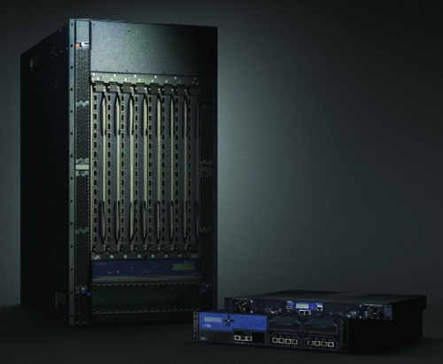
Juniper’s PTX MPLS-optical supercore switch — completing a cloud play


By  Tom Nolle

Juniper made its second major announcement in two weeks, this time its PTX MPLS-optical supercore switch. The product’s roots probably lie in early interest (“early” meaning the middle of the last decade) by Verizon in a new core architecture for IP networks that would eliminate the transit routing that was common in hierarchical IP cores. Since then, everyone from startups (remember Corvus?) to modern players like Alcatel-Lucent, Ciena, and Cisco have been announcing some form of optical-enabled core. What makes Juniper’s PTX different?

Good question, and it’s not easy to answer it from the Juniper’s announcement, but I’d say that the differentiator is the chipset. Junos Express appears to be the same basic chip used in the recently announced QFabric data center switch. Thus, you could say that the PTX is a based on a low-latency MPLS switching architecture that’s more distributed than QFabric. Given what we perceive as a chipset link between the products, I’m creating a term to describe this: Express Domain. An “Express Domain” is a network domain that’s built using devices based on the Express chipset. A PTX network is an Express Domain in the WAN and QFabric is an Express Domain within a data center.

If you look at the PTX that way, then what Juniper is doing is creating an Express Domain linked by DWDM and running likely (at least initially) in parallel with other lambdas that still carry legacy TDM traffic. It becomes less about having an optical strategy than it is about creating a WAN-scale fabric with many of the deterministic features of QFabric. Over time, operators would find their TDM evolving away and would gradually migrate the residual to TDM-over-packet form, which would then make the core entirely an Express Domain. The migration would be facilitated by the fact that the latency within an Express Domain is lower (because packet handling can be deterministic, as it is with QFabric) and because the lower level of jitter would mean it’s easier to make TDM-over-packet technology work. Overall performance of the core would also improve. In short, we’d have something really good for none of the reasons that have been covered so far in the media.

This (if my interpretation is right) is a smart play for Juniper. It creates an MPLS-based virtual domain that can be mapped to anything from a global core to a data center. Recall that I noted in the QFabric announcement that Juniper had indicated that QFabrics could be interconnected via IP/MPLS. Clearly they could be connected with PTXs, and that would create a supercloud and not just a supercore.
What would make it truly revolutionary, of course, would be detailed articulation of cloud-hosting capability. I think that capability exists, but it’s not showing up at the right level of detail in the positioning so far. In any event, if you add PTX to QFabric in just the right way, you have a cloud—probably the best cloud you can build in today’s market.

If Juniper exploits the Express Domain concept, then the PTX and QFabric combine to create something that’s top-line valuable to the service providers. Yes, there are benefits to convergence on packet optical core networks, but those benefits are based on cost alone, and cost management isn’t the major focus of operators right now—monetization is. You can’t drive down transport cost per bit enough for it to be a compelling benefit in overall service pricing, or enough to make low-level services like broadband Internet profitable enough.

Furthermore, achieving significant capex savings for the operator means achieving fewer total sales for the vendor. That’s the old “cost-management-vanishes-to-a-point” story. But you can do stuff at the service layer that was never possible before, drive up the top line, and sell more gear overall rather than less. Or so I think. We’ll be asking for clarification on these points, and in our March Netwatcher we’ll report on what we find.

Sunday, March 20, 2011

JUNOS Certification Tracks


Juniper Networks Education Services is completing the Junos-based curriculum and Juniper Networks Certification Program (JNCP) certifications for the Service Provider Routing and Switching (SP), Enterprise
Routing and Switching (ENT), and Junos Security (SEC) tracks.

The following new written, scenario-based certification exams will be released, which complete the Professional-level of the Junos-based certification tracks:

CertificationAvailable
JNCIP-SECApril, 2011
JNCIP-SPMay, 2011
JNCIP-ENTMay, 2011


Certification
Available
JNCIP-SEC
April, 2011
JNCIP-SP
May, 2011
JNCIP-ENT
May, 2011


CertificationAvailable
JNCIP-SECApril, 2011
JNCIP-SPMay, 2011
JNCIP-ENTMay, 2011


The following new lab-based certification exams will be released, which complete the Expert-level of the Junos-based certification tracks:

CertificationAvailable
JNCIE-SECJune, 2011
JNCIE-SPJuly, 2011
JNCIE-ENTAugust, 2011


CertificationAvailable
JNCIE-SECJune, 2011
JNCIE-SPJuly, 2011
JNCIE-ENTAugust, 2011


Certification
Available
JNCIE-SEC
June, 2011
JNCIE-SP
July, 2011
JNCIE-ENT
August, 2011


Juniper Networks Defines the New Converged Supercore Architecture that Can Dramatically Improve Network Economics for Service and Content Providers

With IP traffic growing in scale and diversity (apps, mobile, cloud) traffic is more dynamic than ever, leading to uncertainty in traffic patterns and volumes through core service provider networks – which usually comprise a 3 layer network of optical, circuit switching, and IP/MPLS, each of which has unique requirements for redundancy, requires independent provisioning, and usually has a separate team managing it.

Juniper Networks has approached this challenge by collapsing layers – resulting in a new converged supercore architecture comprising silicon, systems and software to give unprecedented scale, simplicity, and operational efficiency. The company invested US$40Million to build a Junos Express chipset optimized for transport, which can scale to 3.8 Petabits with optimized MPLS transport logic, unique transport algorithms and full delay bandwidth buffer to manage network congestion. The company also created the purpose-built Juniper PTX Series Converged Supercore Switch - incorporating the efficiency of native MPLS packet switching and integrated optics for high speed, long distance optical transport. With the Converged Supercore, there is no longer a three layered network with three operating systems and three network management platforms: the single Junos operating system runs both the supercore and the services edge and a single state-of-the-art network management system to manage the entire transport network.

The company claims that the combined Junos Express/PTX Series offering delivers 4X the speed of any competitor core platform, 5X the packet processing capability of any competitor core platform, 10X the system scale of any competitor core platform, and industry-leading density at 10G, 40G, and 100G, with integrated short- and long-haul optics; as well as 69% less power consumption than any competitor core platform: to deliver 40-65% capital expenditure (CAPEX) savings compared to a circuit switched network and 35% savings vs. a pure IP routing solution.

Wednesday, March 16, 2011

100G Ethernet stays pricey as speed needs soar

Data centers may need faster links soon, but the new technology is still young

Virtualization, video and massive amounts of data are all driving enterprises and service providers toward 100-Gigabit Ethernet, but the cost of the fledgling technology remains prohibitively high and few products have been installed, industry observers said at the Ethernet Technology Summit.

The 100GE standard was ratified by the IEEE last year, but the technology is just beginning to creep into use. Analyst Michael Howard of Infonetics Research estimates that only a few hundred ports of 100GE have been delivered and most of those are being used by service providers in tests or trials.

However, with the growing amounts of data going in and out of servers in big data centers, some large enterprises also are running into a need for something faster than 10-Gigabit or 40-Gigabit Ethernet, Howard said at the Ethernet Technology Summit this week in Santa Clara, California. Virtualization allows servers to run at higher utilization rates, and blade server chassis pack more computing power into a rack. Connecting these systems to top-of-rack switches, and linking those to other switches at the end of a row, is starting to require multiple 10-gigabit links in some cases, he said.

The Mayo Clinic is already testing 100GE as a possible replacement for multiple 10-Gigabit Ethernet links in its data center, which are needed because its virtualized servers can drive so much traffic onto the clinic's LAN. One reason is that Mayo doctors frequently consult with other physicians around the world and need to share medical imaging files such as CAT scans and MRIs, said Gary Delp, a systems analyst at Mayo.

Aggregated 10-Gigabit ports are still an inefficient way to create fast links within the data center, and 100GE should be more efficient, Delp said. He expects vendors to come out with aggregation technology that pushes traffic more efficiently, and whether users adopt that or 100GE will be a matter of economics, he said.
Some other large enterprises are in similar situations, according to Howard. Using four to eight aggregated links also typically takes up more space and power and generates more heat than a single high-speed connection does, Howard said. One solution administrators are beginning to use is 40-Gigabit Ethernet, which is somewhat less expensive and more readily available today, but the traffic curve points to a need for 100GE, he said.

Cost is one of the main barriers to adoption of 100-Gigabit Ethernet and is likely to remain so for the next few years, Howard said. Though per-port prices can vary based on specific deals, the cost of a 100GE port is still effectively six figures. Juniper Networks typically charges about ten times the cost of a 10-Gigabit Ethernet port, meaning 100GE can cost about US$150,000 per port, a company executive said on Tuesday. Brocade Communications announced a two-port module with the new technology for $194,995 last year. It can be ordered now and is expected to start shipping in the first half of this year, the company said Wednesday.

Tuesday, March 15, 2011

Internet2 Accelerates to 100 Gigabit

Internet2 is moving to 100 Gigabit per second (100G) networking thanks to new technologies and standards. Internet2 is a high-speed network connecting over 50,000 research and educational facilities.
The official move to 100G networking should not come as a surprise, as Internet2 first announced its 100G intentions back in 2008. What has changed in the last two years is that 100G networking has moved from becoming just an idea to becoming an implementable reality.
 
"In 2008 Internet2, ESnet and our partners were really trying to help the market realize the need for 100G capabilities being driven by the research and education community," Rob Vietzke, Internet2 Executive Director of Network Services told InternetNews.com. "Our goal was to push faster adoption of 100G standards and get ready for the deployment that we are now beginning this year."

Vietzke added that today vendors are shipping 100G transponders for DWDM (define) systems as well as 100G interfaces for routers. Availability of 100G equipment is linked to the fact that the IEEE 40/100 Gigabit Ethernet standard was ratified in June.
 
"Another thing that has changed is that scientists involved in big science projects like the Large Hadron Collider are already delivering huge data flows that require these expanded capabilities," Vietzke said.
Internet2 will be using equipment from Juniper Networks in order to build out its 100G infrastructure. Luc Ceuppens, Vice President of Product Marketing, Juniper Networks told InternetNews.com that Internet2 currently has T1600 core routers in service. He add that Internet2 is currently deploying the new 100G network on a region-by-region basis and expects to complete deployment in 2013. The T1600 is Juniper's flagship core routing platform. A 100G line card for the T1600 was announced by Juniper back in June of 2009.
 
Internet2's new 100G enabled network will actually have a total network capacity that dwarfs current systems. Back in 2008, Vietzke told InternetNews.com that Internet2 was running a 100 gigabit per second backbone by utilizing ten 10 Gbps waves.
 
"The new network that will be built will include between 5 and 8 terabits of capacity, based on the latest 100G DWDM systems and Juniper's T1600 routers," Vietzke said "It will have capability for at least fifty 100G waves and include a national scale 100G Ethernet service on the T1600 on day one."
In terms of cost, Juniper declined to comment on the specific value of the deployment of their gear to Internet2. That said, Vietzke noted that Internet2 has received funding from the U.S. government for the effort.
 
"Internet2 has been very fortunate to receive a $62.5M American Reinvestment and Recovery Act investment that will help support this project and deliver next generation network capabilities not only to our existing community but to as many as 200,000 community anchor institutions across the country," Vietzke said.

Saturday, March 12, 2011

Trends reshaping networks

By Network World

Server and storage environments have seen a lot of changes in the past ten years, while developments in networking have remained fairly static. Now the demands of virtualization and network convergence are driving the emergence of a host of new network developments.  Here’s what you need to know and how to plan accordingly.

* Virtualization. Virtualization has allowed us to consolidate servers and drive up utilization rates, but virtualization is not without its challenges.  It increases complexity, causing new challenges in network management, and has a significant impact on network traffic.

Prior to virtualization, a top of rack (ToR) switch would support network traffic from 20-35 servers, each running a single application. With virtualization, each server typically hosts 4-10 VMs, resulting in 80 to 350 applications being supported by a single ToR rather than multiples switches, consolidating the network traffic. As a result, the ToR is much more susceptible to peaks and valleys in traffic, and given the consolidation of traffic on one switch, the peaks and valleys will be larger. Network architectures need to be designed to support these very large peaks of network traffic.

* Flattening the network. It is not possible to move VMs across a Layer 3 network, so the increased reliance on VMs is driving the need to move toward flattening the network – substituting Layer 2 architecture for older Layer 3 designs. In addition, a flatter network reduces latency and complexity, often relying only on ToR switches or end of row (EoR) switches connected to core switches. The result is lower capital expenses as fewer switches need to be purchased, the ability to migrate VMs across a larger network, and a reduction in network latency.

* TRILL. To facilitate implementation of Layer 2 networks, several protocols have emerged. One major change is the replacement of Spanning Tree Protocol (SPT). Since there are usually multiple paths from a switch to a server, SPT handled potential multipath confusion by setting up just one path to each device. However, SPT limits the network bandwidth and as the need developed for larger Layer 2 networks, SPT has become too inefficient to do the job.

Enter the Transparent Interconnection of Lots of Links (TRILL). TRILL is a new way to provide multipath load balancing within a Layer 2 fabric and is a replacement for SPT. TRILL has been defined by IETF and maps to 802.1q capabilities within the IEEE. TRILL eliminates the need to reserve protected connections for future use, and thereby stranding bandwidth.

* Virtual physical switch management. In a virtualized environment, virtual switches typically are run on servers to provide network connectivity for the VMs in the server. The challenge is each virtual switch is another network device that must be managed. Additionally, the virtual switch is often managed through the virtualization management software. This means the virtualization administrator is defining the network policies for the virtual switch while the network administrator is defining the network policies for the physical switch. This creates potential problems as two people are defining network policies. Since it is critical to have consistent security and flow control policies across all switches, this conflict must be resolved.

* EVB (Edge Virtual Bridging) is an IEEE standard that seeks to address this management issue. EVB has two parts, VEPA and VN-Tag. VEPA (Virtual Ethernet Port Aggregator) offloads all switching from the virtual switch to the physical switch. All network traffic from VMs goes directly to the physical switch. Network policies defined in the switch, including connectivity, security and flow control, are applied to all traffic.

If the data is to be sent to another VM in the same server, the data is sent back to the server via a mechanism called a hairpin turn. As the number of virtual switches increases, the need for VEPA increases because the virtual switches require more and more processing power from the server. By offloading the virtual switch function onto physical switches, therefore, VEPA removes the virtualization manager from switch management functions, returns processing power to the server, and makes it easier for the network administrator to achieve consistency for QoS, security, and other settings across the entire network architecture.

In addition to VEPA, the IEEE standard also defined multi-channel VEPA, which defines multiple virtual channels, allowing a single physical Ethernet connection to be managed as multiple virtual channels.
The second part of EVB is VN-Tag. VN-Tag was originally proposed by Cisco as an alternative solution to VEPA. VN-Tag defines an additional header field in the Ethernet frame that allows individual identification for virtual interfaces. Cisco has already implemented VN-Tag in some products.

* VM migration. In a virtualized data center, VMs are migrated from one server to another to support hardware maintenance, disaster recovery or changes in application demand.

When VMs are migrated, VLANs and port profiles need to be migrated as well to maintain network connectivity, security and QoS (Quality of Service). Today, virtualization administrators must contact network administrators to manually provision VLANs and port profiles when VM’s are migrated. This manual process can greatly impact the data center flexibility as this manual process could take minutes, hours or days, depending on the network administrator’s workload.

Automated VM/network migration addresses this problem. With automated VM/network migration, the VLAN and port profiles are automatically migrated when a VM is migrated. This eliminates the need for network administrators to do this manually, ensuring that VM/network migration is completed immediately.

* Convergence. The other major trend underway in data center networking is fabric convergence. IT managers want to eliminate separate networks for storage and servers. With fabric convergence they can reduce management overhead and save on equipment, cabling, space and power. Three interrelated protocols that enable convergence are Fibre Channel over Ethernet (FCoE), Ethernet itself (which is being enhanced with Data Center Bridging (DCB), and 40/100GB Ethernet.

Storage administrators initially gravitated to Fibre Channel as a storage networking protocol because it is inherently lossless, as storage traffic can’t tolerate any loss in transmission. FCoE encapsulates Fibre Channel traffic onto Ethernet and allows administrators to run storage and server traffic on the same converged Ethernet fabric. FCoE allows network planners to retain their existing FCoE controllers and storage devices while migrating to a converged Ethernet network for transport. This eliminates the need to maintain two entirely separate networks.

DCB comes into the picture because it enhances Ethernet to make it a lossless protocol, which is required for it to carry FCoE. A combination of FCoE and DCB standards will have to be implemented both in converged NICs and in data center switch ASICs before FCoE is ready to serve as a fully functional standards-based extension and migration path for Fibre Channel SANs in high performance data centers.
Another advancement being driven by the rise in server and storage traffic on the converged network is the move to 40GB and 100GB Ethernet. With on-board 10GbE ports expected to be available on servers in the near future, ToR switches need 40GB Ethernet uplinks or they may become network bottlenecks.

Preparing for the Future

Some of the protocols discussed are still in development, but that doesn’t mean you shouldn’t begin planning now to leverage them.  Here are some ways to prepare for the changes:

* Understand these technologies and determine if they are important to implement.

* Evaluate when to incorporate these new technologies. While you may not have the need today, you should architect the data center network to allow for future upgrades.
Plan for open standards. Data center network architectures should be based on open standards. This gives customers the most flexibility. Proprietary products lock customers into a vendor’s specific products. Products based on open standards give customers architectural freedom to incorporate future technologies when they become available and when it makes sense for the business.

* Plan on upgrading to 10GbE sometime in the next year or two, then have a way to upgrade to 40/100GbE when prices fall. The 10GbE price per port is expected to fall significantly next year, driving a significant increase in 10GB port installations.

It is clear the network is becoming a dynamic part of a virtual computing stack. Plan now to stay ahead of the dynamic changes reshaping the data center.

Cisco SP NGN Innovation Breadth and Depth

This slide shows the different equipment used at Application, Service and Network layers.


Sunday, March 6, 2011

The Juniper QFabric FAQ

by Tim Greene
Juniper Networks has introduced its new data center architecture called QFabric, which promises improved performance and economy. Here are some questions and answers about the new technology.

What is QFabric?

It is Juniper’s new data center architecture that creates a single logical switch that connects the entire data center rather than tiers of multiple access aggregation and core switches.

Why is that an advantage?

It improves performance by reducing latency, which is accomplished by getting rid of layers of switches and cutting the number of devices needed, which also reduces the demand for space and power as well as management and maintenance.

What devices make up QFabric?

The architecture deconstructs a traditional switch into three component parts, an ingress-egress platform called a node, an interconnect platform corresponding to a switch backplane and a management platform that gives a single view of the fabric.

How does this flatten the architecture?

The node has switching and routing intelligence about all relevant paths through the fabric and makes Layer 2 and 3 forwarding decisions. Since nodes are logically connected peers, there is no need for aggregating ports with banks of access switches that feed aggregation switches that feed core switches. Packets are switched directly to the appropriate egress port.

Why is this fabric faster?

Packets are processed once and forwarded to the appropriate port without having to be reprocessed at every layer of a hierarchical architecture. Packets get through the infrastructure in a single hop. Juniper says delay is  5 microsec  maximum across a data center at maximum cable length. Shorter lengths yield 3.71 microsec delay, which Juniper says is less than in a chassis-based Ethernet switch.

How does QFabric deal with congestion?

With its knowledge of other nodes, each node can sense congestion as it develops and adjust its forwarding rate accordingly. Juniper won’t say exactly how this mechanism works because it is trying to patent it, but it promises that the whole fabric is lossless even under congestion.

What is the practical result of this congestion control?

By dealing with congestion dynamically and quickly, QFabric gets rid of the need to over design the network to accommodate it. That boosts network utilization to near 100%, Juniper says.

What are some numbers on how well this fabric performs?

The average data center – defined by IDC as having 3,000 servers – using QFabric rather than a traditional three-tiered architecture is six times faster, requires 22%fewer devices overall and incurs half the operating expenses.

Does this have implications for cloud architecture?

Yes, but not immediately. Juniper says that it will announce later a means to incorporate WAN connections into QFabric, making it possible to link dispersed data centers to support cloud services.

Saturday, March 5, 2011

It’s Here: Revealing the QFabric™ Architectu​re


by Juniper Employee


QFabric-Logo.jpg


At last the big day is here!  Juniper has been talking about the power of a data center fabric for two years, since we first publicly disclosed the existence of Project Stratus.  We’ve discussed why we were building a fabric and what it would mean to our customers.  But we have intentionally been silent on the specifics of the architecture and the underlying technological magic.

That changes today.  In simultaneous locations around the world, we are sharing the secrets of QFabric, the fruit of the Stratus project, via webcast; and introducing the first component of the fabric, the QFX3500 Switch.

A few hundred years ago, a Franciscan friar named William of Ockham professed a concept that today is known as Occam's Razor.  He stated that when confronted with multiple alternatives, the simplest path is usually the correct one.  That is the defining concept behind QFabric.  Pradeep Sindhu, our founder and spiritual leader, looked at the data center network and saw a simpler, more correct path to solve this most difficult of network problems.  We believe the path he chose can eventually transform every data center in the world.

I have written extensively on why flat fabrics are the only natural solution for interconnecting the infrastructure of the modern data center.  Other vendors are attempting to build data center fabrics using their existing Ethernet switching components, but instead of focusing on the network, they focused on their switches.  It’s like being a brick manufacturer and deciding to build a high-rise building in California entirely out of bricks.  It is possible; it’s just a really bad idea.

The Simplest Path

Pradeep took a clean sheet approach, the simplest path.  That it would be a flat fabric was a given.  That it would adhere to network standards and not change the way applications, servers, storage, and other infrastructure components connect to the network was also a given.  Where the brilliance lies is in the inherent simplification of the network.  Push the intelligence to the edge of the fabric.  Minimize the amount of processing and hardware required to transport data across the fabric while maintaining any-to-any connectivity.  Enable the fabric to scale from tens of ports to thousands or even tens of thousands of ports while maintaining the simplest and most proven operational model—that of a single switch.

The challenge with describing new products that fundamentally transform the world around them is placing them in the right context to discuss and measure the revolution.  Simply put, the QFabric delivers the performance and operational simplicity of a single switch while delivering the scale and resilience of a network.  We believe there is nothing else like it in the world.

To achieve this, Pradeep and the architects rethought almost every aspect of a switch.  The resulting innovation is captured in more than 125 new patent applications filed as part of the project.

Design Principles of QFabric

QFabric is built on three design principles:

  1. Build a data plane that ensures any-to-any connectivity across the entire data center while minimizing network processing.  This requires pushing the intelligence necessary to process incoming packets and handle  the complexity of the real world to the edge of the fabric, The interior of the fabric focuses on merely “transporting” the bits—a simpler, less costly activity.  This is the only way to enable the fabric to economically scale across the entire data center while delivering the blazing performance and low jitter required by modern applications.
  2. Build a control plane that distributes and federates the real-time control of the fabric, placing the intelligence that controls the fabric into every edge node to ensure low latencies and inherent resilience.  Then provide an out-of-band control plane to ensure the federation of this intelligence, enabling the fabric to behave as a single switch without resorting to flooding, without worrying about or managing loops, and without needing to run spanning tree or a Trill.
  3. Build a management plane on top of the control plane that automates and abstracts the operation of the fabric while presenting the simplest and best understood operational model to the administrator—that of a single switch.  This is not a network management application that enables a single pane of glass to manage multiple autonomous switches.  QFabric is in fact a single switch.

The result is a fabric that:

  • Is blazingly fast.  In an internal test we found that QFabric can deliver sub five-microsecond latency across an entire data center.  And that is assuming maximum length interconnect cables which add more than one microsecond of that latency due to the speed of light.  With shorter cables we have measured latencies as low as 3.7 microseconds.  That QFabric is the world’s fastest fabric (over 500 ports) is a given.  What may be a surprise is that QFabric is faster than any chassis-based Ethernet switch ever built. And the fabric is consistently fast, delivering extremely low jitter under load.

    • Scales in a linear fashion from tens to more than 6,000 10GbE ports. In the future, we also plan to deliver mega-fabrics that will scale to tens of thousands of ports and micro-fabrics that scale under 1000 ports.  It’s a fabric for data centers of all sizes.

    • Delivers the ultimate in operational simplicity.  Because QFabric behaves as a single switch, it is possible to manage the entire fabric with a single network operator. 

    • Delivers a quantum change in the total cost of ownership.  This is not the normal puffery of marketing; QFabric is more efficient because of its design.  Reducing the processing elements required to build the fabric not only makes it fast but reduces manufacturing costs.  Fewer hardware elements also require less power, cooling, and floor space.  Fewer hardware elements also mean greater reliability and lower support costs.  And finally, the inherent simplicity of the fabric will reduce management costs.  Hard to beat that.

    Introducing the QFX3500

    Today we also introduced the QFX3500, a remarkable new product that not only serves as the edge node of the QFabric, but can also function as a standalone, 48-port 10GbE top-of-rack data center access switch.  It too is blazingly fast, delivering under 780 nanoseconds of latency.  We recently teamed with IBM to run the STAC benchmark which measures application throughput and latency on a financial services workload; the result showed the fastest Ethernet performance ever recorded and only one microsecond slower than Infiniband. With the QFX3500, you can start by implementing a more traditional network topology, have it interoperate with any existing vendor’s infrastructure and upgrade to QFabric when you are ready.

    What does this mean to the business?

    While great technology is fascinating, at least to me, what does QFabric mean to the business?  It's quite simple:  QFabric will unleash the true power of the data center.  A fast fabric will enable every application to perform better, delivering a better user experience.  A flat, scalable, transparent fabric delivers a more elastic data center and ultimately greater business agility.  And the inherent simplicity of QFabric enables the entire data center to operate more efficiently and reliably.  Better experience and better economics.  What more could you ask for?

    Friday, March 4, 2011

    Load - All about JUNOS load command

    Syntax

    load (factory-default | merge | override | patch | replace | set | update) (filename | 
    terminal) <relative>
    

    Description

    Load a configuration from an ASCII configuration file, from terminal input, or from the factory default. Your current location in the configuration hierarchy is ignored when the load operation occurs.

    Required Privilege Level

    configure—To enter configuration mode; other required privilege levels depend on where the statement is located in the configuration hierarchy.

    Options

    factory-default—Loads the factory configuration. The factory configuration contains the manufacturer's suggested configuration settings. The factory configuration is the router's first configuration and is loaded when the router is first installed and powered on.
    On J-series Services Routers, pressing and holding down the Config button on the router for 15 seconds causes the factory configuration to be loaded and committed. However, this operation deletes all other configurations on the router; using the load factory-default command does not.

    filename—Name of the file to load. For information about specifying the filename, see Specifying Filenames and URLs.

    merge—Combine the configuration that is currently shown in the CLI and the configuration in filename.

    override—Discard the entire configuration that is currently shown in the CLI and load the entire configuration in filename. Marks every object as changed.

    patch—Change part of the configuration and mark only those parts as changed.

    replace—Look for a replace: tag in filename, delete the existing statement of the same name, and replace it with the configuration in filename.

    set—Merge a set of commands with an existing configuration. This option executes the configuration instructions line-by-line as they are stored in a file or from a terminal. The instructions can contain any configuration mode command, such as set, edit, exit, and top.

    relative—(Optional) Use the merge or replace option without specifying the full hierarchy level.

    terminal—Use the text you type at the terminal as input to the configuration. Type Ctrl+d to end terminal input.

    update—Discard the entire configuration that is currently shown in the CLI, and load the entire configuration in filename. Marks changed objects only.

    Thursday, March 3, 2011

    Juniper attacks core networking market with Stratus QFabric


    Networking company Juniper has released a new technology weapon — its Stratus QFabric switches and architecture — to conquer the core network switching space.

    Released three days ago in late February 2011 in a worldwide launch, Juniper’s QFabric architecture is claimed by them to be a technologically superior way to implement network architectures, yielding both higher performance and significantly lower costs.

    Lam Chee Kiong, enterprise solutions manager for Asia Pacific at Juniper Networks explained that an ideal network architecture has a few key attributes like low latency, high reliability and scalability. These are typically implemented in a three tier networking framework, with core switches being surrounded by access switches and edge routers.

    Juniper’s QFabric architecture aims to do away with this.


    In the most extreme scenario he presented, a network architecture with 6000 server ports, he compared a Juniper QFabric architecture with a traditional Cisco architecture.

    Juniper claims that with their architecture they can shrink hundreds of devices into a far smaller footprint — four chasis racks — consuming 90 percent less floor space and using 66 per cent less power.

    On top of that, in their scenario, they project that their network speeds will be up to fifteen times faster and require far less management devices — one as compared to hundreds.

    This is done by consolidating all the QFabric switches and allowing them to be plugged in directly to the QFabric interconnects. An analogy would be to think of the QFabric architecture as a series of blade servers, but instead of computing or storage, it is for networking solutions.

    Attacking Cisco in the data centre space

    With the worldwide network switching market’s year-on-year growth at 28.1 per cent for 2010, and a total valuation at US$21.1 billion according to research firm IDC, the future prospects look bright for Juniper.
    Indeed, Juniper’s last quarterly earnings beat analysts’ expectations and showed a 26.4 per cent year-on-year increase in revenue. With it’s Stratus QFabric launch, Juniper is poised to do potentially even better, and will threaten longtime rival Cisco’s share in the core network switching space.

    Juniper believes the QFabric solution will play well in the data center space as cloud computing and virtualization are two forces driving adoption. Both floor space and power consumption are big issues here, as well as the latency speed issues that the QFabric architecture solves.

    Said Chee Kiong, who estimates that data centres comprise 20 percent of the core network switching market: “The battleground is pitched at the data centre, because if it’s good enough here [to meet the stringent requirements], it’s good enough for other deployments.”

    In Asia Pacific, Chee Kiong is targeting two industries in particular: financial institutions and government. Banks require extremely low latency and robust solutions, and governments tend to house huge complex solutions which the QFabric can help more easily manage.

    The QFabric QFX3500 switch ships this quarter and is undergoing customer trials, and the full QFabric architecture — like the interconnects and control plane — will be available in Q3 2011.

    Juniper took hundreds of million of dollars and a million hours of R&D to develop the QFabric architecture, which started three years back in 2009 under project Stratus.

    Juniper Password Recovery

    1. From console, interrupt the boot routine:

    Hit [Enter] to boot immediately, or any other key for command prompt.
            Booting [kernel] in 9 seconds...
    
    < Press the space bar at this point >
    

    1. Enter into single-user mode:
    Type '?' for a list of commands, 'help' for more detailed help.
            ok boot -s
    

    1. Enter the shell:
    1. For new JunOS releases, the system will prompt:
    "Enter full pathname of shell or 'recovery' for root password recovery or RETURN for /bin/sh: "
    
    If you enter "recovery" at this point, it will do the next two steps for you, and leave you in the JunOS CLI, from where you can edit the root password.
    1. Mount the virtual file systems (for JUNOS 5.4 and above, it is not necessary to mount the jbase (or jcrypto) package, however the other packages still need to be mounted):
    NOTE: to go to multi-user operation, exit the single-user shell
    
    (with ^D)
    # cd /packages
            # ./mount.jbase
            Mounted jbase package on /dev/vn1...
            # ./mount.jkernel
            Mounted jkernel package on /dev/vn2...
            # ./mount.jroute
            Mounted jroute package on /dev/vn3...
    

    1. Enter recovery mode:
    # /usr/libexec/ui/recovery-mode
    

    1. Enter configuration mode and either delete or change the root
    authentication password:

    root> configure
            Entering configuration mode
    
    [edit]
            root# delete system root-authentication
    
    1. Commit the changes, and exit configuration mode
    [edit]
            root # commit
            commit complete
    
    [edit]
            root@router# exit
            Exiting configuration mode
    
    root@router> exit
    

    Exit recovery mode and enter "y" when prompted to reboot the system:
    Reboot the system? [y/n] y
            Terminated
    
    The system now reboots and changes made to root authentication are activated.

    Wednesday, March 2, 2011

    QFabric Network Pitches Juniper Against Cisco

    Juniper’s QFabric networking architecture collapses the traditional three-layer data centre infrastructure

    Juniper Networks is rolling out a new networking platform executives say will simplify the data centre infrastructure, driving up throughput, scalability and efficiency while reducing latency, operating costs and the number of devices required for a networking architecture. During a Webcast event from San Francisco, Juniper executives unveiled their QFabric architecture, an $100 million initiative formerly called “Project Stratus” that was launched after three years of development.

    The goal of the project is to collapse the data centre networking infrastructure from the traditional two or three layers down to one, a move that will enable enterprises and mid-size businesses handle the demands created by the onset of cloud computing and the growth of the mobile Internet.

    “As these trends accelerate, its creates exponential demand, and it’s that exponential demand that requires a new approach,” Juniper CEO Kevin Johnson said during the event.

    Challenging Cisco’s Data Centre Domination


    QFabric also gives Juniper a higher profile in the highly competitive data centre networking space, a market still dominated by Cisco Systems, but with a cadre of rivals trying to grab a larger share. Juniper still needs to continue to build on its initiative, but the QFabric push is a strong step, according to Forrester Research analyst Andre Kindness.

    “Even though Juniper still needs to deliver on parts 2 and 3, this product launch moves them up and puts Juniper Networks back in the Data Centre Derby with Arista, Avaya, Brocade, and Cisco,” Kindness said in a February 23 blog post. “Juniper’s vision overlaps layer 3 and 2, which keeps packets from running across fabric for something that can be done locally thereby eliminating waste. The design allows partitioning of network by workgroup, too. QFabric’s strongest differentiation is the single management plane that makes all the components behave as one switch without introducing a single failure point. Juniper’s QFabric drives simplicity into the data centre, a value long overdue.”

    The QFabric architecture essentially enables network administrators to manage the networking infrastructure as a single switch, with a single view of the fabric. Three components make up the low-latency, high-performance fabric, including the QF/Node, which Juniper executives said is the distributed decision engine. In addition, the QF/Interconnect is a high-speed transport device, while the QF/Director gives network administrators a single, common window through which they can control all devices as a single one.
    “It doesn’t just behave as a single switch, it is a single switch,” David Yen, executive vice president and general manager of Juniper’s switching business, said.

    Juniper unveiled the QFX3500 node is the first product in the QFabric product portfolio, and will be available later this quarter. Initially, it will work as a traditional 10 Gigabit Ethernet, though it will become more of a node in the QFabric architecture later in the year. The QF/Interconnect and QF/Director will be available for order in the third quarter.

    Johnson and other Juniper executives said QFabric will offer a host of benefits for businesses. It will be up to 10 times faster than legacy networks, use 77 percent less power, require 27 percent fewer networking devices, and occupy 90 percent less data centre floor space.

    “These are significant numbers that don’t come about every day,” Pradeep Sindhu, founder and CTO of Juniper, said during the event.

    SIndhu noted that because Juniper’s products support Ethernet and Fibre Channel, businesses will be able to gradually adopt the QFabric architecture, replacing competing products with Juniper offerings when needed. He also said that while QFabric is aimed at the internal data centre, Juniper later this year will offer technology that will enable a network architecture that can be used over the WAN to connect multiple data centres.

    Juniper’s rollout comes at a time of transition for Cisco. For the past two years, Cisco aggressively has been expanding its reach beyond its networking base, growing into such areas as servers – with its UCS (Unified Computing System) – collaboration technologies and smart grid solutions. Some analysts have argued that doing so has taken the company’s focus away from its networking solutions, giving competitors like Juniper, Hewlett-Packard and Avaya an opening to gain ground in the market.

    While some of those markets saw growth for Cisco in the past quarter, revenues in the core switching business declined. Still, Cisco executives are confident in their data centre strategy.

    “Cisco’s standards-based architectural approach combining unified computing, a unified fabric, and unified network services provides a stronger foundation than fragmented point-product approaches,” John McCool, vice president and general manager for Cisco’s Data Centre, Switching and Services Group, said in a statement. “For example, the Nexus platform supports a unified fabric and we announced last June Nexus 7000 FabricPath, a standards-based ‘flat network’ solution to accelerate virtualisation and cloud computing. We’ve also built our network platforms with investment protection in mind… the Nexus platform, like the Catalyst before it, was designed to deliver innovative new capabilities and services for many years without the need to ever rip and replace.”

    Cost per Incident

    “how do you determine cost per incident?”

    Cost per incident is a variation of cost per call or cost per contact, all of which are excellent ways to understand the impact of incidents, calls, or contacts on the business.

    The calculation is fairly straightforward. Cost per incident is the total cost of operating your support organization divided by the total number of incidents for a given period (typically a month).

    Cost per incident = total costs/total incidents

    To accurately calculate cost per incident you must:
    • Log all incidents. You may also find it beneficial to distinguish between incidents (unplanned events) and service requests (planned events). Such a distinction will enable you to more accurately reflect business impact
    • Identify stakeholders. Determine all of the support people involved in the incident management process (e.g., service desk and level two/three technical and application management teams). 
    • Identify associated costs. Create a list of every cost associated with your stakeholders including salaries, benefits, facilities, and equipment. Many of these costs will be included in your annual budget or can be obtained from financial management.
    As illustrated in the ROI calculator, tremendous cost savings can be realized by reducing the number of incidents. This can be accomplished by using trend and root cause analysis techniques via the problem management process, as well as through integration with processes such as change management, service asset and configuration management, and release and deployment management.

    Savings can also be realized by reducing the number of incidents escalated from the service desk to other lines of support, or by increasing the number of incidents handled via self-help services such as a web-based knowledge management system. Some organizations report on cost per incident per channel (e.g., per call, e-mail, chat, walkup) to better understand these savings.

    My Blog List

    Networking Domain Jobs