Network Enhancers - "Delivering Beyond Boundaries" Headline Animator

Thursday, February 28, 2013

Remote Management Services: Rethinking the Way You Manage and Operate IT


Just a few short years ago, if your car broke down, you would automatically take it to your local mechanic who would identify the issue and fix it. Fast forward to 2013 – today we live in an era where our cars tell US when there is a potential issue or it needs a service and, more often than not, they just don’t break down at all. We’ve gone from a reactive, break-fix model to a proactive and, sometimes, even a pre-emptive approach, or warranty as they call it. It’s the technology – specifically the software embedded in our cars and the software that supports and maintains it from the manufacturer – that has fundamentally changed this industry.

There is a similar shift happening in IT. Customer care-abouts are evolving from simply, “make my technology work” to “make my business better.” Drivers such as cloud and mobility are causing us to pause and rethink our traditional approaches and consider new ways to both consume and manage IT. As more and more business and IT activities move into the cloud, the services needed to keep everything running seamlessly become ever more critical.

Services can help companies maintain IT health and, by providing expertise and support, can support this transition to cloud as customer and partners explore new opportunities. Services – in the form of automation, analytics and software – play a crucial role in both extracting more value out of existing infrastructure and driving innovation in new areas. How?

I recently spoke about Cisco’s Smart Services, which use intelligent automation to collect network data, then analyze that data using Cisco’ s deep knowledge base to provide actionable insight to customer and partners. These software-enabled services automate network operations, reduce risk and lower costs – top priorities for any organization, regardless of size.

SmartServices

Remote Management Services

Remote Management Services (RMS), part of Cisco Smart Service portfolio, provide comprehensive, proactive remote network monitoring and management. These services are being used today by a range of companies and employs smart-based capabilities, together with Cisco’s deep knowledge and expertise, to help organisations:
  • Quickly adopt and deploy new architecture-based technologies
  • Reduce the cost of hiring and training
  • Complement the skill sets of IT management staff
  • Ensure network availability and performance
  • Move the operational SLA’s from reactive to pre-emptive
This automated approach means that the software identifies current or future problems and deals with them automatically. In addition to solving issues more efficiently, RMS frees up valuable labour resources to focus attention to more strategic issues. RMS also saves money by being able to repeat processes and reuse the same methodologies, with low variance and minimal error.

So, who would use RMS?

All businesses today are under increasing pressure — facing budget and resource constraints — yet are still expected to deliver more value to the business.

In general, the compelling event driving an RMS conversation is, indeed, resources — whether it is lack of headcount, the need for different skillsets, a requirement for structured processes and appropriate tools, or a combination of these. Another driver for RMS is the need to adopt advanced or emerging networking technologies where there is a gap in relevant internal expertise. In either case, when Cisco and RMS become involved, the customer can improve operations and availability, and is able to refocus their valuable internal IT resources more strategically.

We’re already seeing the value RMS can bring to customers.

For example, Cisco, with support from RMS, helped a large global financial services organization return to ‘business as usual’ across multiple sites in a disaster recovery situation. We were able to not only have the business back up and running, but also rebuilt their IP telephony and replaced several thousand handsets in a matter of days.

In another case, RMS has been utilized with a global retailer to provide a fully integrated experience to reduce voice solution complexity for a combined environment. This has enabled the customer to move to a single managed services contract for voice and data based on Cisco technology with business, financial and technology SLAs – leading to increased efficiencies and reduced costs.
As large data, cloud computing, BYOD and mobility, and a new breed of software applications continue to reshape the IT landscape, networks will require ever more intelligence and, therefore, the services to effectively cope with further complexity and maintain the platform on which we increasingly rely.

With Services, we can do this automatically, using software – now, that’s Smart!


Wednesday, February 27, 2013

Wireless 101 - Part 2


Antenna

An antenna is a device to transmit and/or receive electromagnetic waves. Electromagnetic waves are often referred to as radio waves. Most antennas are resonant devices, which operate efficiently over a relatively narrow frequency band. An antenna must be tuned (matched) to the same frequency band as the radio system to which it is connected otherwise reception and/or transmission will be impaired.

Types of antenna

There are 3 types of antennas used with mobile wireless, omnidirectional, dish and panel antennas.
+ Omnidirectional radiate equally in all directions
+ Dishes are very directional
+ Panels are not as directional as Dishes.


Decibels

Decibels (dB) are the accepted method of describing a gain or loss relationship in a communication system. If a level is stated in decibels, then it is comparing a current signal level to a previous level or preset standard level. The beauty of dB is they may be added and subtracted. A decibel relationship (for power) is calculated using the following formula:

dB_formula.jpg

“A” might be the power applied to the connector on an antenna, the input terminal of an amplifier or one end of a transmission line. “B” might be the power arriving at the opposite end of the transmission line, the amplifier output or the peak power in the main lobe of radiated energy from an antenna. If “A” is larger than “B”, the result will be a positive number or gain. If “A” is smaller than “B”, the result will be a negative number or loss.

You will notice that the “B” is capitalized in dB. This is because it refers to the last name of Alexander Graham Bell.

Note:

+ dBi is a measure of the increase in signal (gain) by your antenna compared to the hypothetical isotropic antenna (which uniformly distributes energy in all directions) -> It is a ratio. The greater the dBi value, the higher the gain and the more acute the angle of coverage.

+ dBm is a measure of signal power. It is the the power ratio in decibel (dB) of the measured power referenced to one milliwatt (mW). The “m” stands for “milliwatt”.

Example:

At 1700 MHz, 1/4 of the power applied to one end of a coax cable arrives at the other end. What is the cable loss in dB?

Solution:

dB_example.jpg

=> Loss = 10 * (- 0.602) = – 6.02 dB

From the formula above we can calculate at 3 dB the power is reduced by half. Loss = 10 * log (1/2) = -3 dB; this is an important number to remember.

Beamwidth

The angle, in degrees, between the two half-power points (-3 dB) of an antenna beam, where more than 90% of the energy is radiated.

beamwidth.jpg

OFDM

OFDM was proposed in the late 1960s, and in 1970, US patent was issued. OFDM encodes a single transmission into
multiple sub-carriers. All the slow subchannel are then multiplexed into one fast combined channel.

The trouble with traditional FDM is that the guard bands waste bandwidth and thus reduce capacity. OFDM selects channels that overlap but do not interfere with each other.

FDM_OFDM.gif

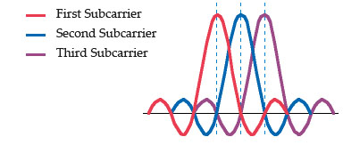
OFDM works because the frequencies of the subcarriers are selected so that at each subcarrier frequency, all other subcarriers do not contribute to overall waveform.

In this example, three subcarriers are overlapped but do not interfere with each other. Notice that only the peaks of each subcarrier carry data. At the peak of each of the subcarriers, the other two subcarriers have zero amplitude.

OFDM.jpg

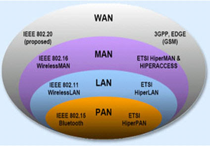
Types of network in CCNA Wireless

+ A LAN (local area network) is a data communications network that typically connects personal computers within a very limited geographical (usually within a single building). LANs use a variety of wired and wireless technologies, standards and protocols. School computer labs and home networks are examples of LANs.

+ A PAN (personal area network) is a term used to refer to the interconnection of personal digital devices within a range of about 30 feet (10 meters) and without the use of wires or cables. For example, a PAN could be used to wirelessly transmit data from a notebook computer to a PDA or portable printer.

+ A MAN (metropolitan area network) is a public high-speed network capable of voice and data transmission within a range of about 50 miles (80 km). Examples of MANs that provide data transport services include local ISPs, cable television companies, and local telephone companies.

+ A WAN (wide area network) covers a large geographical area and typically consists of several smaller networks, which might use different computer platforms and network technologies. The Internet is the world’s largest WAN. Networks for nationwide banks and superstore chains can be classified as WANs.

types_of_network.jpg

Bluetooth

Bluetooth wireless technology is a short-range communications technology intended to replace the cables connecting portable and/or fixed devices while maintaining high levels of security. Connections between Bluetooth devices allow these devices to communicate wirelessly through short-range, ad hoc networks. Bluetooth operates in the 2.4 GHz unlicensed ISM band.

Note:

Industrial, scientific and medical (ISM) band is a part of the radio spectrum that can be used by anybody without a license in most countries. In the U.S, the 902-928 MHz, 2.4 GHz and 5.7-5.8 GHz bands were initially used for machines that emitted radio frequencies, such as RF welders, industrial heaters and microwave ovens, but not for radio communications. In 1985, the FCC Rules opened up the ISM bands for wireless LANs and mobile communications. Nowadays, numerous applications use this band, including cordless phones, wireless garage door openers, wireless microphones, vehicle tracking, amateur radio…

WiMAX

Worldwide Interoperability for Microwave Access (WiMax) is defined by the WiMax forum and standardized by the IEEE 802.16 suite. The most current standard is 802.16e.

Operates in two separate frequency bands, 2-11 GHz and 10-66 GHz
At the higher frequencies, line of sight (LOS) is required – point-to-point links only
In the lower region, the signals propagate without the requirement for line of sight (NLOS) to customers

Basic Service Set (BSS)

A group of stations that share an access point are said to be part of one BSS.

Extended Service Set (ESS)

Some WLANs are large enough to require multiple access points. A group of access points connected to the same WLAN are known as an ESS. Within an ESS, a client can associate with any one of many access points that use the same Extended service set identifier (ESSID). That allows users to roam about an office without losing wireless connection.

IEEE 802.11 standard

A family of standards that defines the physical layers (PHY) and the Media Access Control (MAC) layer.

* IEEE 802.11a: 54 Mbps in the 5.7 GHz ISM band
* IEEE 802.11b: 11 Mbps in the 2.4 GHz ISM band
* IEEE 802.11g: 54 Mbps in the 2.4 GHz ISM band
* IEEE 802.11i: security. The IEEE initiated the 802.11i project to overcome the problem of WEP (which has many flaws and it could be exploited easily)
* IEEE 802.11e: QoS
* IEEE 802.11f: Inter Access Point Protocol (IAPP)

More information about 802.11i:

The new security standard, 802.11i, which was ratified in June 2004, fixes all WEP weaknesses. It is divided into three main categories:

1. Temporary Key Integrity Protocol (TKIP) is a short-term solution that fixes all WEP weaknesses. TKIP can be used with old 802.11 equipment (after a driver/firmware upgrade) and provides integrity and confidentiality.
2. Counter Mode with CBC-MAC Protocol (CCMP) [RFC2610] is a new protocol, designed from ground up. It uses AES as its cryptographic algorithm, and, since this is more CPU intensive than RC4 (used in WEP and TKIP), new 802.11 hardware may be required. Some drivers can implement CCMP in software. CCMP provides integrity and confidentiality.
3. 802.1X Port-Based Network Access Control: Either when using TKIP or CCMP, 802.1X is used for authentication.

Wireless Access Points

There are two categories of Wireless Access Points (WAPs):
* Autonomous WAPs
* Lightweight WAPs (LWAPs)

Autonomous WAPs operate independently, and each contains its own configuration file and security policy. Autonomous WAPs suffer from scalability issues in enterprise environments, as a large number of independent WAPs can quickly become difficult to manage.

Lightweight WAPs (LWAPs) are centrally controlled using one or more Wireless LAN Controllers (WLCs), providing a more scalable solution than Autonomous WAPs.

Encryption

Encryption is the process of changing data into a form that can be read only by the intended receiver. To decipher the message, the receiver of the encrypted data must have the proper decryption key (password).

TKIP

TKIP stands for Temporal Key Integrity Protocol. It is basically a patch for the weakness found in WEP. The problem with the original WEP is that an attacker could recover your key after observing a relatively small amount of your traffic. TKIP addresses that problem by automatically negotiating a new key every few minutes — effectively never giving an attacker enough data to break a key. Both WEP and WPA-TKIP use the RC4 stream cipher.

TKIP Session Key

* Different for every pair
* Different for every station
* Generated for each session
* Derived from a “seed” called the passphrase

AES

AES stands for Advanced Encryption Standard and is a totally separate cipher system. It is a 128-bit, 192-bit, or 256-bit block cipher and is considered the gold standard of encryption systems today. AES takes more computing power to run so small devices like Nintendo DS don’t have it, but is the most secure option you can pick for your wireless network.

EAP

Extensible Authentication Protocol (EAP) [RFC 3748] is just the transport protocol optimized for authentication, not the authentication method itself:

” EAP is an authentication framework which supports multiple authentication methods. EAP typically runs directly over data link layers such as Point-to-Point Protocol (PPP) or IEEE 802, without requiring IP. EAP provides its own support for duplicate elimination and retransmission, but is reliant on lower layer ordering guarantees. Fragmentation is not supported within EAP itself; however, individual EAP methods may support this.” — RFC 3748, page 3

Some of the most-used EAP authentication mechanism are listed below:

* EAP-MD5: MD5-Challenge requires username/password, and is equivalent to the PPP CHAP protocol [RFC1994]. This method does not provide dictionary attack resistance, mutual authentication, or key derivation, and has therefore little use in a wireless authentication enviroment.
* Lightweight EAP (LEAP): A username/password combination is sent to a Authentication Server (RADIUS) for authentication. Leap is a proprietary protocol developed by Cisco, and is not considered secure. Cisco is phasing out LEAP in favor of PEAP.
* EAP-TLS: Creates a TLS session within EAP, between the Supplicant and the Authentication Server. Both the server and the client(s) need a valid (x509) certificate, and therefore a PKI. This method provides authentication both ways.
* EAP-TTLS: Sets up a encrypted TLS-tunnel for safe transport of authentication data. Within the TLS tunnel, (any) other authentication methods may be used. Developed by Funk Software and Meetinghouse, and is currently an IETF draft.
*EAP-FAST: Provides a way to ensure the same level of security as EAP-TLS, but without the need to manage certificates on the client or server side. To achieve this, the same AAA server on which the authentication will occur generates the client credential, called the Protected Access Credential (PAC).
* Protected EAP (PEAP): Uses, as EAP-TTLS, an encrypted TLS-tunnel. Supplicant certificates for both EAP-TTLS and EAP-PEAP are optional, but server (AS) certificates are required. Developed by Microsoft, Cisco, and RSA Security, and is currently an IETF draft.
* EAP-MSCHAPv2: Requires username/password, and is basically an EAP encapsulation of MS-CHAP-v2 [RFC2759]. Usually used inside of a PEAP-encrypted tunnel. Developed by Microsoft, and is currently an IETF draft.

RADIUS

Remote Authentication Dial-In User Service (RADIUS) is defined in [RFC2865] (with friends), and was primarily used by ISPs who authenticated username and password before the user got authorized to use the ISP’s network.

802.1X does not specify what kind of back-end authentication server must be present, but RADIUS is the “de-facto” back-end authentication server used in 802.1X.

Roaming

Roaming is the movement of a client from one AP to another while still transmitting. Roaming can be done across different mobility groups, but must remain inside the same mobility domain. There are 2 types of roaming:

A client roaming from AP1 to AP2. These two APs are in the same mobility group and mobility domain

Roaming_Same_Mobile_Group.jpg

Roaming in the same Mobility Group

A client roaming from AP1 to AP2. These two APs are in different mobility groups but in the same mobility domain

Roaming_Different_Mobile_Group.jpg
 

Monday, February 25, 2013

Wireless 101 - Part 1


In this article we will discuss about Wireless technologies mentioned in CCNA.

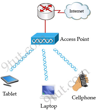
Wireless LAN (WLAN) is very popular nowadays. Maybe you have ever used some wireless applications on your laptop or cellphone. Wireless LANs enable users to communicate without the need of cable. Below is an example of a simple WLAN:

Wireless_Applications.jpg

Each WLAN network needs a wireless Access Point (AP) to transmit and receive data from users. Unlike a wired network which operates at full-duplex (send and receive at the same time), a wireless network operates at half-duplex so sometimes an AP is referred as a Wireless Hub.


The major difference between wired LAN and WLAN is WLAN transmits data by radiating energy waves, called radio waves, instead of transmitting electrical signals over a cable.

Also, WLAN uses CSMA/CA (Carrier Sense Multiple Access with Collision Avoidance) instead of CSMA/CD for media access. WLAN can’t use CSMA/CD as a sending device can’t transmit and receive data at the same time. CSMA/CA operates as follows:

+ Listen to ensure the media is free. If it is free, set a random time before sending data
+ When the random time has passed, listen again. If the media is free, send the data. If not, set another random time again
+ Wait for an acknowledgment that data has been sent successfully
+ If no acknowledgment is received, resend the data

IEEE 802.11 standards:

Nowadays there are three organizations influencing WLAN standards. They are:

+ ITU-R: is responsible for allocation of the RF bands
+ IEEE: specifies how RF is modulated to transfer data
+ Wi-Fi Alliance: improves the interoperability of wireless products among vendors

But the most popular type of wireless LAN today is based on the IEEE 802.11 standard, which is known informally as Wi-Fi.

* 802.11a: operates in the 5.7 GHz ISM band. Maximum transmission speed is 54Mbps and approximate wireless range is 25-75 feet indoors.
* 802.11b: operates in the 2.4 GHz ISM band. Maximum transmission speed is 11Mbps and approximate wireless range is 100-200 feet indoors.
* 802/11g: operates in the 2.4 GHz ISM band. Maximum transmission speed is 54Mbps and approximate wireless range is 100-200 feet indoors.

ISM Band: The ISM (Industrial, Scientific and Medical) band, which is controlled by the FCC in the US, generally requires licensing for various spectrum use. To accommodate wireless LAN’s, the FCC has set aside bandwidth for unlicensed use including the 2.4Ghz spectrum where many WLAN products operate.

Wi-Fi: stands for Wireless Fidelity and is used to define any of the IEEE 802.11 wireless standards. The term Wi-Fi was created by the Wireless Ethernet Compatibility Alliance (WECA). Products certified as Wi-Fi compliant are interoperable with each other even if they are made by different manufacturers.


Access points can support several or all of the three most popular IEEE WLAN standards including 802.11a, 802.11b and 802.11g.

WLAN Modes:

WLAN has two basic modes of operation:

* Ad-hoc mode: In this mode devices send data directly to each other without an AP.

Wireless_Ad-hoc_mode.jpg

* Infrastructure mode: Connect to a wired LAN, supports two modes (service sets):

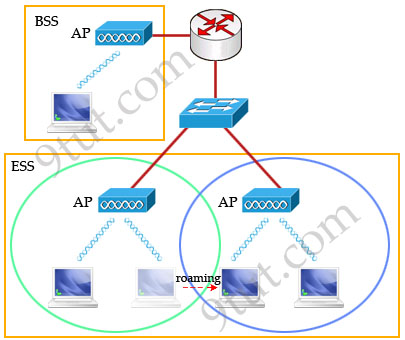
+ Basic Service Set (BSS): uses only a single AP to create a WLAN
+ Extended Service Set (ESS): uses more than one AP to create a WLAN, allows roaming in a larger area than a single AP. Usually there is an overlapped area between two APs to support roaming. The overlapped area should be more than 10% (from 10% to 15%) to allow users moving between two APs without losing their connections (called roaming). The two adjacent APs should use non-overlapping channels to avoid interference. The most popular non-overlapping channels are channels 1, 6 and 11 (will be explained later).

Wireless_Infrastructure_mode.jpg

Roaming: The ability to use a wireless device and be able to move from one access point’s range to another without losing the connection.

When configuring ESS, each of the APs should be configured with the same Service Set Identifier (SSID) to support roaming function. SSID is the unique name shared among all devices on the same wireless network. In public places, SSID is set on the AP and broadcasts to all the wireless devices in range. SSIDs are case sensitive text strings and have a maximum length of 32 characters. SSID is also the minimum requirement for a WLAN to operate. In most Linksys APs (a product of Cisco), the default SSID is “linksys”.

Wireless Encoding

When a wireless device sends data, there are some ways to encode the radio signal including frequency, amplitude & phase.


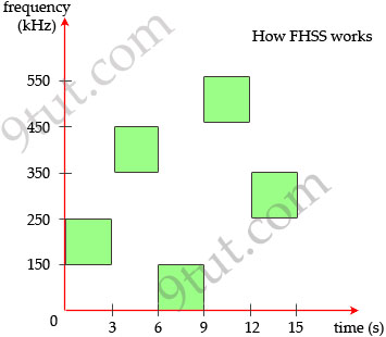
Frequency Hopping Spread Spectrum(FHSS): uses all frequencies in the band, hopping to different ones after fixed time intervals. Of course the next frequency must be predetermined by the transmitter and receiver.

Frequency_Hopping_Spread_Spectrum_FHSS.jpg

The main idea of this method is signals sent on different frequencies will be received at different levels of quality. By hopping to different frequencies, signals will be greatly improved the possibility that most of it will get through. For example, suppose there is another device using the 150-250 kHz range. If our device transmits in this range then the signals will be significantly interfered. By hopping at different frequencies, there is only a small interference while transmitting and it is acceptable.

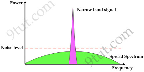
Direct Sequence Spread Spectrum (DSSS): This method transmits the signal over a wider frequency band than required by multiplying the original user data with a pseudo random spreading code. The result is a wide-band signal which is very “durable” to noise. Even some bits in this signal are damaged during transmission, some statistical techniques can recover the original data without the need for retransmission.

Note: Spread spectrum here means the bandwidth used to transfer data is much wider than the bandwidth needs to transfer that data.

Traditional communication systems use narrowband signal to transfer data because the required bandwidth is minimum but the signal must have high power to cope with noise. Spread Spectrum does the opposite way when transmitting the signal with much lower power level (can transmit below the noise level) but with much wider bandwidth. Even if the noise affects some parts of the signal, the receiver can easily recover the original data with some algorithms.

wireless_Spread_Spectrum_Signal.jpg

Now you understand the basic concept of DSSS. Let’s discuss about the use of DSS in the 2.4 GHz unlicensed band.

The 2.4 GHz band has a bandwidth of 82 MHz, with a range from 2.402 GHz to 2.483 GHz. In the USA, this band has 11 different overlapping DSSS channels while in some other countries it can have up to 14 channels. Channels 1, 6 and 11 have least interference with each other so they are preferred over other channels.

wireless_2_4_GHz_band.png

Orthogonal Division Multiplexing (OFDM): encodes a single transmission into multiple sub-carriers to save bandwidth. OFDM selects channels that overlap but do not interfere with each other by selecting the frequencies of the subcarriers so that at each subcarrier frequency, all other subcarriers do not contribute to overall waveform.

In the picture below, notice that only the peaks of each subcarrier carry data. At the peak of each of the subcarriers, the other two subcarriers have zero amplitude.

wireless_OFDM.jpg

Below is a summary of the encoding classes which are used popularly in WLAN.

Encoding Used by
FHSS The original 802.11 WLAN standards used FHSS, but the current standards (802.11a, 802.11b, and 802.11g) do not
DSSS 802.11b
OFDM 802.11a, 802.11g, 802.11n


WLAN Security Standards

Security is one of the most concerns of people deploying a WLAN so we should grasp them.

Wired Equivalent Privacy (WEP)

WEP is the original security protocol defined in the 802.11b standard so it is very weak comparing to newer security protocols nowadays.

WEP is based on the RC4 encryption algorithm, with a secret key of 40 bits or 104 bits being combined with a 24-bit Initialisation Vector (IV) to encrypt the data (so sometimes you will hear “64-bit” or “128-bit” WEP key). But RC4 in WEP has been found to have weak keys and can be cracked easily within minutes so it is not popular nowadays.

The weak points of WEP is the IV is too small and the secret key is static (the same key is used for both encryption and decryption in the whole communication and never expires).

Wi-Fi Protected Access (WPA)

In 2003, the Wi-Fi Alliance developed WPA to address WEP’s weaknesses. Perhaps one of the most important improvements of WPA is the Temporal Key Integrity Protocol (TKIP) encryption, which changes the encryption key dynamically for each data transmission. While still utilizing RC4 encryption, TKIP utilizes a temporal encryption key that is regularly renewed, making it more difficult for a key to be stolen. In addition, data integrity was improved through the use of the more robust hashing mechanism, the Michael Message Integrity Check (MMIC).

In general, WPA still uses RC4 encryption which is considered an insecure algorithm so many people viewed WPA as a temporary solution for a new security standard to be released (WPA2).

Wi-Fi Protected Access 2 (WPA2)

In 2004, the Wi-Fi Alliance updated the WPA specification by replacing the RC4 encryption algorithm with Advanced Encryption Standard-Counter with CBC-MAC (AES-CCMP), calling the new standard WPA2. AES is much stronger than the RC4 encryption but it requires modern hardware.

Standard Key Distribution Encryption
WEP Static Pre-Shared Weak
WPA Dynamic TKIP
WPA2 Both (Static & Dynamic) AES

Wireless Interference

The 2.4 GHz & 5 GHz spectrum bands are unlicensed so many applications and devices operate on it, which cause interference. Below is a quick view of the devices operating in these bands:

+ Cordless phones: operate on 3 frequencies, 900 MHz, 2.4 GHz, and 5 GHz. As you can realize, 2.4 GHz and 5 GHz are the frequency bands of 802.11b/g and 802.11a wireless LANs.

Most of the cordless phones nowadays operate in 2.4 GHz band and they use frequency hopping spread spectrum (FHSS) technology. As explained above, FHSS uses all frequencies in the the entire 2.4 GHz spectrum while 802.11b/g uses DSSS which operates in about 1/3 of the 2.4 GHz band (1 channel) so the use of the cordless phones can cause significant interference to your WLAN.

wireless_cordless_phone.jpg

An example of cordless phone

+ Bluetooth: same as cordless phone, Bluetooth devices also operate in the 2.4 GHz band with FHSS technology. Fortunately, Bluetooth does not cause as much trouble as cordless phone because it usually transfers data in a short time (for example you copy some files from your laptop to your cellphone via Bluetooth) within short range. Moreover, from version 1.2 Bluetooth defined the adaptive frequency hopping (AFH) algorithm. This algorithm allows Bluetooth devices to periodically listen and mark channels as good, bad, or unknown so it helps reduce the interference with our WLAN.

+ Microwaves (mostly from oven): do not transmit data but emit high RF power and heating energy. The magnetron tubes used in the microwave ovens radiate a continuous-wave-like at frequencies close to 2.45 GHz (the center burst frequency is around 2.45 – 2.46 GHz) so they can interfere with the WLAN.

+ Antenna: There are a number of 2.4 GHz antennas on the market today so they can interfere with your wireless network.

+ Metal materials or materials that conduct electricity deflect Wi-Fi signals and create blind spots in your coverage. Some of examples are metal siding and decorative metal plates.

+ Game controller, Digital Video Monitor, Wireless Video Camera, Wireless USB may also operate at 2.4 GHz and cause interference too.

Saturday, February 16, 2013

Intel Invests in Big Switch


Big Switch Networks is announcing Friday that Intel Capital is an investor, a pairing that suggests the rise of so-called white-box switches -- generic systems built with off-the-shelf chips -- might be imminent.
 
Big Switch isn't quite wording it that way. (In fact, executives declined to say anything about their plans.) But the company has made no secret of its disdain for the current state of networking, where big vendors (primarily Cisco Systems Inc.) dominate the market with proprietary systems based on ASICs.
 
"There's a clear trend toward horizontalization -- getting away from the model where everything comes pre-integrated from one vendor," says Guido Appenzeller, Big Switch's CEO. Any of the "hyperscale" Web/cloud players -- the likes of Google, Facebook, Amazon Web Services LLC -- have "at least tried" some form of horizontal development in the data center, he says.
 
Intel invested $6.5 million in Big Switch's Series B funding, bringing Big Switch's total funding to more than US$45 million. The Series B round itself was announced in October and included investors Redpoint Ventures and Goldman Sachs & Co. (See Big Switch Raises $25M for OpenFlow Push.)
 
It's not hard to see why Intel is interested. Big Switch is developing applications that take advantage of the OpenFlow protocol, which theoretically could replace the routing or switching software that's in a box from a company like Cisco.
 
That would be a major step toward producing white-box switches. Another major piece required would be the Ethernet switching chip itself. Broadcom Corp. leads that market, but Intel, with the 2011 acquisition of Fulcrum Microsystems, is trying hard to strengthen its footing there.
 
An ecosystem around white boxes is starting to emerge. Pica8 Inc. recently came out with its reference design for such a switch. So did Intel, for that matter: a design called Seacliff Trail that was announced in September. (See Buying Into the New Cisco.)
 
If you needed any more evidence that white-box switching is working up a head of steam, some big data-center owners (Google, for instance) and large financial institutions are proclaiming their interest in the concept. They're uniting their voices into the Open Networking Users Group (ONUG), which is convening Feb. 13 in Boston. (Note: Google isn't part of ONUG.)
 
"You will see some of the largest customers in the world demanding some very specific mandates, one of which is standardization, which implies white boxes," says Jason Matlof, Big Switch's vice president of marketing.
 
Cisco has countered that ASICs will remain crucial to high-end systems. It's preaching a different vision of software-defined networking (SDN) based on application programming interfaces (APIs) reaching into different layers of the network -- but it's also started warming to the idea of having its switches support OpenFlow. (See Cisco Extends Its SDN & Cloud Plans and Juniper's SDN Will Build Service Chains.)
 
But getting back to the original point: It's clear Intel Capital isn't investing in Big Switch just for kicks. The idea was championed inside Intel by the Fulcrum group, after they got acquired in 2011, Matlof says.
 
Of course, Intel was familiar with Big Switch before then, as were all the major chip vendors. Appenzeller has been talking SDN with them since 2008, when he took over the OpenFlow project at Stanford University.
 

Friday, February 15, 2013

F5 Buys Layer 7 SDN Specialist

 
F5 Networks Inc. is the latest company to acquire a software-defined networking (SDN) startup, announcing Monday morning that it's picked up LineRate Systems Inc. for an undisclosed price.
Based near Boulder, Colo., LineRate offers software for Layer 7 SDN. That is, LineRate Proxy software provides a programmable way to handle traffic at the application layer; the company's website lists policy-based traffic management as an example.
 
Unlike some SDN acquisition targets, LineRate isn't brand new. The company is four years old and claims PhotoBucket as a customer, as GigaOm reported last year. Ironically, the avoidance of "expensive special-purpose F5 machines" was an advantage to using LineRate, according to the story.
 
Why this matters
The SDN conversation has broadened beyond routing and switching to include Layers 4 through 7. Startup Embrane Inc. is trying to specialize in that area, for instance.
 
But F5 believes that those layers can't be handled in the same way as Layers 2 and 3, because at the application layer, the network has to keep track of the state of a flow.
 
As Lori MacVittie, F5 senior technical marketing manager, explains in her Monday blog posting, a Layer 7 operation might need to forward most packets to a centralized controller. OpenFlow (as an example of a Layer 2 SDN protocol) assumes only very few packets will need to be handled by the controller.
 
So, F5 believes a different structure is needed for Layer 7. The company seems to think LineRate has at least part of the answer.
 

Wednesday, February 13, 2013

Best Practices - Data Center Upgrades Without the Downtime

 
The data center reflects the fortunes of the business it supports and, as such, has its own cycle of growth and consolidation. Greater usage and data throughput means more servers and racks; this, in turn, means more heat and power issues, which inevitably lead to a need for upgrades or a consolidation of the center itself. Add to this the emerging environmental and energy-consumption regulations, and it is easy to understand why data center managers find themselves in a state of almost perpetual change. Although a new, purpose-built facility always offers an attractive solution to accommodating these demands, it is in fact rarely an option. Because of the cost and disruption issues associated with new construction, retrofitting and live upgrades account for the vast majority of change in the data center, outpacing new construction by a ratio of around three to one.
So how do you prepare for a successful upgrade without downtime?
 

Think About the Business, Not the IT

 
The first, and most important step is to understand that live upgrade is a business issue rather than an IT issue. The choice of a live upgrade is driven by demands on the business to minimize cost and disruption. Therefore, in this context aligning the planning and preparation for the live upgrade to the business itself is of paramount importance.
This approach is very much in the interests of the business as well. A quick checklist of the risks to core business processes that could stem from a failure in the data center makes a convincing case: communications, email, customer accounts and services, the maintenance of an auditable data trail, and many others should convince any board that a live upgrade is a crucial business project.

Properly Supply the Project

Establishing the live upgrade as something that is not “business as usual” should enable you to avoid the most common mistake made by organizations considering such projects: making the IT department wholly responsible for its planning and execution. To make this mistake represents a failure to understand that an IT department’s inherent strength is its consistency and resilience as a service provider. It does not necessarily follow that the IT department should also offer, from its existing resources, the project and change-management skills that are absolutely essential for a successful upgrade. A live upgrade requires a lot of planning across the business. In fact, the project is usually 80% preparation and 20% execution, and as one CTO said, “If my staff had the time to plan a data center upgrade, then I’d know I was overstaffed!”
 
There are four distinct phases of preparation that must always precede the upgrade itself.
 
Phase One: Communicate
 
Although a properly functioning data center rarely has many visitors, it does have many stakeholders. These stakeholders comprise the various parts of the business that depend on the data center to support their processes, and when you begin to contemplate an upgrade, you must start with a communications program that engages with all of them. The program should also include the contractors, third-party support organizations, the project team and any others who hold responsibility for the data center environment. Identify your stakeholders, tell them how the upgrade project will affect them and win their support.
 
Phase Two: Understand Your Environment
 
A thorough audit of your IT environment will help you gain a deep understanding of the demands of the project. Different technologies have different requirements, so you should not assume one size fits all—for example, hot and cold aisles work well for some servers, but not if they draw air from the side. Some equipment, such as a SAN, is very heavy, so make sure you know what the requirements are and plan accordingly. Similarly, consider cable lengths when planning the equipment layout.
 
Phase Three: Plan the plan
 
For the project to be successful, you need to take the business with you. This means listening and understanding the challenges that your colleagues face across the business and planning the work in manageable chunks to suit their needs as well as your own. As you move from planning to execution, establish site control and ensure there is a statement of work (SOW) for each activity. The best approach is to regularly test and validate the plan and be prepared to compromise.
 
Phase Four: Mitigate the Risk
 
Impact assessments for each element of the work are an invaluable tool for managing risk throughout the project. These assessments should anticipate the effects of the work itself and plan for the dust and rubbish that will inevitably be produced; failure here could present the biggest risk of all. A live upgrade is as much about change management as it is about IT, so if your business has a process you should use it. Additionally, ensure that the data center’s backup regime is reviewed before embarking on the project. This should include a review of its physical and logical security as well and the business continuity plan—after all, the data center is about to become a building site!
 
In conclusion, the live upgrade of a data center is not a business-as-usual activity; a typical project may last 6 to 12 months. The data center must support the business for 6 to 12 years. The years between upgrades will involve significant changes both in technology and best practice, so accessing external resources for the project brings the benefit of state-of-the-art specialist knowledge as well as the additional people needed to get the job done on schedule. External expertise—whether consultants or contractors—should offer project-management skills, specialist knowledge, and data center operations experience as well; after all you don’t want them to deliver you a newly refurbished data center that is impossible to operate!
 

Tuesday, February 12, 2013

RCom, Ericsson make $1 billion managed services deal


Reliance Communications Limited signed an eight-year full-scope managed services agreement with Ericsson today for USD 1 billion to operate and manage the wireline and wireless networks for northern and western states of India.


As per the contract, Ericsson will manage the day to day operations across wireline and wireless networks and will take over responsibility for field maintenance, network operations and operational planning of Reliance Communications 2G, CDMA and 3G mobile networks. This agreement is aimed to meet the fast evolving customer demand for communications applications and services in one of the world’s most dynamic telecom markets.


Reliance Communications will benefit from Ericsson’s proven world-class processes, methods and tools and the partnership will allow Reliance Communications to free up resources to focus on user experience, as well as improving innovation power, agility and speed across the specified geographies. Reliance Communications’ infrastructure covers 24,000 towns and 600,000 villages in India to which it offers converged services including voice, data and video.
 

This is one of the first converged wireless and wireline managed services contract in India, and one of only a handful in the world. Ericsson will streamline Reliance Communication’s operations by bringing all aspects of Fiber, Tower Operations, Wireless Networks and Wireline Access networks to RCom’s wireless and Global Enterprise Business, across differentiated product lines. Ericsson will also drive a modernization of the tools, processes and best practices that are applied across the business resulting in operational efficiencies by managing cost through consolidation.

Commenting on the agreement, Gurdeep Singh, Chief Executive Officer – Wireless Business, Reliance Communications, said, “We are happy to announce our partnership with Ericsson to manage our wireline and wireless network enabling us to provide a higher level of customer experience in terms of network and services. Given the complexity of network increasing with platforms, technologies and application offerings, we are banking on the experience, innovation and technical expertise of Ericsson to improve the productivity of our network and ensure that it delivers to its full potential. We are confident that they will exceed the expectations of our customers through optimization of resources and provide us cost effective solutions.”

Magnus Mandersson, Executive Vice President and Head of Business Unit Global Services, Ericsson, said, “We are excited to partner with Reliance Communications for this strategic multi-technology managed services deal. The increasing uptake of new technologies requires an increased focus on customer experience management in the hyper competitive and highly dynamic Indian telecom market. With this partnership Reliance will increase focus on their core business and innovation. We are pleased to welcome more than 5,000 employees who will join us from Reliance Communications and support our long term commitment to India’s ICT market.”

This agreement with Ericsson will be driven by defined Service Level Agreement governance. Ericsson will be responsible for improving network performance and ultimately service quality, with the goal of increasing customer satisfaction and retention. Ericsson will also work closely with Reliance Communications to identify opportunities to introduce new services and expand its existing businesses to help realize the full potential of its network.

“This partnership will enable our enterprise customers to deploy state-of-the-art data services on our integrated network through the global expertise of Ericsson. This is one of the first times that wireless and wireline enterprise network is being outsourced to deliver world-class service and performance assurance,” added Punit Garg, Chief Executive Officer, Global and Enterprise Business, Reliance Communications.

Fredrik Jejdling, Head of Region India, Ericsson, said, “Ericsson has been telecom partner in India for the past 110 years. With this agreement, we expand our footprint and strengthen our existing leadership in Managed Services.” Adding emphasis to the importance of people, Jejdling mentioned that Ericsson is gearing up to welcome Reliance employees and ensure they are well-integrated into the company’s local and global services organisation.
 

Monday, February 11, 2013

CCNA Video - New Cisco certifications


Highlighting the increasing use of high-quality video traffic over the network, Cisco announced the release of the Cisco CCNA Video and Cisco Video Network Specialist certifications. CCNA Video is designed for video professionals who design, install and support video solutions on Video-Voice-over-IP networks.

The new Cisco Video Network Specialist certification enables traditional analog audiovisual (Pro A/V) specialists, as well as other networking professionals, to extend their skills to meet the growing demand for networked video job roles.

These programs expand career opportunities for employees of enterprise, government, service provider and reseller partner organizations transitioning from other areas such as routing and switching, voice and unified communications to video networking.

CCNA Video

A job-role-focused training and certification program, CCNA Video establishes an individual’s ability to deploy video endpoints, set up new users, and operate networked voice and video solutions for job duties that include configuring voice and video single-screen endpoint devices, supporting telephony and video applications, and troubleshooting. The certification also validates a candidate’s knowledge of the architecture, components, functionalities and features of Cisco Unified Communications Manager solutions. 

VIVND 200-001 and ICOMM 640-461 exams are requirements for the CCNA Video certification. Recommended training is available from Cisco and authorized Cisco Learning Partners.

Cisco Video Network Specialist

In order to prepare individuals for career opportunities as video technicians, video administrators or audiovisual installers in IP-networked environments, the Cisco Video Network Specialist certification establishes and enhances key skills including the ability to configure video single-screen endpoints, set up new user accounts, support video applications and troubleshoot networked video solutions.

The VIVND 200-001 exam is required for Cisco Video Network Specialist certification.


Sunday, February 10, 2013

Cisco vs. Juniper: How different are their SDN strategies?

 
On the surface, Cisco and Juniper's SDN strategies seem to have sharp contrasts if recent announcements are any indication. For example:
 
• Juniper places much more emphasis on the software angle of SDN, even ushering in a new software licensing business model; Cisco's attempts to make hardware as much, and perhaps even more, relevant than software.

• Cisco is attacking five markets at once -- data center, enterprise, service provider, cloud, academia -- with its strategy, while Juniper is focusing initially on data centers.

• Juniper views SDNs as much more disruptive, potentially allowing it to significantly increase share; Cisco has thus far made no such dramatic market impact statements regarding SDNs.

• As part of its hardware focus on SDN, Cisco is funding a separate spin-in company -- Insieme Networks -- which is believed to be building big programmable switches and controller(s); Juniper has no such hardware investments, but did buy Contrail for $176 million, again emphasizing the software aspect of SDNs.

• Cisco has a timeline of 2013 deliverables; Juniper's timeline pushes a controller and SDN service "chaining" capability out into 2014, and the new software business model into 2015.
 
Yet analysts say there are really more similarities than differences in both strategies from the fierce rivals.

"I think there are some similarities," says Brad Casemore of IDC. "Both Juniper and Cisco are emphasizing ASICs, and therefore hardware, in their SDN strategies. Both companies also see network and security services -- Layer 4-7 -- as virtualized applications in a programmable network.

They each have controllers, but they also will promote hybrid control planes -- decoupled and distributed. Juniper is positioning for a software-licensing business model, true, but it's relatively early along in that process."

"It's a different packaging strategy but both seem equally focused on the value of software in SDN," says Mike Fratto of Current Analysis. "Key points being modular, flexible, and exposing APIs for integration."

Juniper recently divulged its SDN strategy after months of silence - seven months after Cisco announced its Cisco ONE plan. Salient points of Juniper's plan include separating networking software into four planes -- Management, Services, Control and Forwarding -- to optimize each plane within the network; creating network and security service virtual machines by extracting service software from hardware and housing it on x86 servers; using a centralized controller that enables service chaining in software, or the ability to connect services across devices according to business need; and the new software-based licensing model, which allows the transfer of software licenses between Juniper devices and industry-standard x86 servers, and is designed to allow customers to scale purchases based on actual usage.

Cisco's ONE, or Open Networking Environment strategy, includes an API platform to instill programmability into its three core operating systems: IOS, IOS XR and NX-OS. It's focused on five key markets and also includes new programmable ASICs, like the UADP chip unveiled with the new Catalyst 3850 enterprise switch; and a software-based controller for data centers that runs on x86 servers. New ASICs are also expected to be front-and-center when the Cisco-funded Insieme Networks start-up unveils what's expected to be a high-performance programmable switch and controller line.

Juniper's strategy initially targets data centers, and its new software licensing model is based on enterprise practices. The company will expand its traditional carrier and service provider customers from there.

Among the first markets addressed in Cisco's ONE strategy are enterprise customers, data centers and cloud providers.

"Juniper ultimately sees SDN at all layers of the network, spanning not only the data center -- edge/access and core --, but also the WAN, campus and branch," says IDC's Casemore. "Juniper's SDN road map initially targets the SP edge and data center, but it does plan to follow SDN into other areas.

"Cisco sees data center and cloud as near-term markets, and its positioning to play across the board as SDN -- and its outcomes, network virtualization and network programmability -- extends its reach," Casemore says. "Again, there are many similarities."

In terms of market disruption, Fratto says both companies see SDN as perhaps equally disruptive even though one has been much more vocal about that impact than the other.

"I think the two companies view SDN as disruptive but they are approaching it very differently," he says. "Juniper tends to be more conservative in bringing new products to market, particularly with Junos. They have a quarterly software update cycle and they march to that drum. I think they have a strong preference for stability in the platform and based on their consistent messaging on that topic.

"I think for Cisco, the disruption is there but the recent announcements tell a lot about its direction going forward," Fratto continues. "I think it signals ... wanting to be vendor and protocol agnostic vs. promoting their own technology over others. The ONE controller, for example, is modular and will support OnePK and Openflow out of the gate, but there is no reason other than development that it can't support other protocols."

Casemore sees both companies reacting to SDN developments, rather than driving them.

"Neither has led the charge toward SDN. Both are measuring their responses, trying to find a balance between supporting their customers today while preparing for potentially disruptive shifts."

And Casemore sees both equally emphasizing hardware, despite Juniper's software-intensive strategy.

"Juniper has a lot of existing hardware, and hardware customers, that it will attempt to fold into its SDN strategy," he says. "We will see hardware and software from both Cisco and Juniper, as their common ASIC strategies suggest."

And even though the timelines for deliverables differ, they are in keeping with each company's traditions.

"That's Juniper's way, right?" Fratto says. "Produce a road map and then deliver over a longer timeline like 12 to 24 months."

Where the strategies diverge will be in partner ecosystems for SDN-enabled services, he says.
"In both cases, they will need to attract partners into their respective ecosystems. The market for services has a ton of players -- think (application delivery controllers), firewalls, WAN optimization.

For those services to be chained, they have to be integrated with Juniper's stuff. Same for Cisco. That's going to be the attractor."

Casemore sees differences in initial target markets too.

"I look at Juniper's strategy as being more attuned to the SP/carrier community than the enterprise -- their service chaining concept is very close to network functions virtualization -- whereas the strategy and technologies Cisco has rolled out thus far are more enterprise oriented," he says. "That's not to say that Juniper won't develop more of an enterprise orientation or that Cisco won't push its SDN strategy into carriers -- both will happen. But that's how I see them now at this particular snapshot in time."

Friday, February 8, 2013

Introducing Cisco Nexus 6000 Series


Courtesy - Cisco

The evolution of the applications environment is creating new demands on IT and in the data center. Broad adoption of scale-out application architectures (i.e. big data), workload virtualization and cloud deployments are demanding greater scalability across the fabric. The increase in east/west (i.e. server-to-server) traffic along with the higher adoption of 10GbE in the server access layer is driving higher bandwidth requirements in the upstream links.

Following up on the introduction of 40GE/100GE on the Nexus 7000 Series, today we unveil the new Nexus 6000 Series, expanding Cisco’s Unified Fabric data center switching portfolio in order to provide greater deployment flexibility through higher density and scalability in an energy efficient form factor. 
 
The Cisco Nexus 6000 Series is industry’s highest density full-featured Layer 2 / Layer 3 40 Gigabit data center fixed switch with Ethernet and Fiber Channel over Ethernet (FCoE) – an industry first!In addition to high scalability, Nexus 6000 Series offers operational efficiency, superior visibility and agility


HIGHEST SCALABILITY

The Nexus 6000 Series represents a breakthrough innovation in scale – by delivering industry-leading 10GE / 40GE port density in a fixed form factor with Layer 2/Layer 3 and consistently low latency –1 microsecond across all ports.
Two Nexus 6000 models are:
  • Nexus 6004 – Up to 96 line rate 40GE ports or 384 10GE line rate ports in an energy-efficient 4 Rack Unit form factor
  • Nexus 6001 – Line rate 48 1G/10G fixed ports with 4 10G/40G uplinks in a 1 Rack Unit form factor
But delivering the scale you need to evolve as your business grows is more than just port density. The Nexus 6000 supports Cisco FEX technology and FabricPath. If we combine a Nexus 6004 with the new Nexus 2248PQ Fabric Extender, which supports 48 ports of 10 Gig with four 40 Gig uplinks, we can effectively build a solution that supports more than 1500 one Gigabit or 10 Gigabit server ports, all managed from one switch. And it can support over 75,000 virtual machines on a single Nexus 6004 switch with VM-level granular switching (1500 FEX ports * 50 VMs per server).

OPERATIONAL EFFICIENCY and SUPERIOR VISIBILITY

The Nexus 6000 Series is efficient – To help lower operating costs, in addition to space and power efficiency, Nexus 6000 simplifies deployments with power-on auto-provisioning with intelligence to support device-aware provisioning and configuration. 

The Nexus 6000 provides superior visibility – with its analytical framework:
  • Microburst monitoring for ingress and egress ports helps identify application performance during peak activity such as volatile stock market activity to avoid congestion
  • Switch and network latency monitoring with IEEE 1588 helps IT accurately monitor traffic and fine tune the network to optimize application performance
  • SPAN on drop enables further analysis when a packet gets dropped due to congestion
Nexus 6000 provides Smart Buffering such as shared buffering for making efficient usage of the buffer for burst absorption. Nexus 6000 also provides Intelligent Flow Management such as Sampled Netflow for traffic engineering, capacity planning or Priority Flow Control for point-to-point flow control of Ethernet traffic based on IEEE 802.1p CoS. With a flow-control mechanism in place, congestion does not result in drops, transforming Ethernet into a reliable medium. Explicit congestion notification also allows an end-to-end notification of network congestion without dropping packets.

AGILITY

And, the Nexus 6000 Series is agile – to enable customers to accelerate innovation –Python and TCL scripting functionality with future support for onePK enables our customers to achieve automation within their data center environment. 10GE and 40GE FCoE support provides architectural flexibility for deploying converged networks while 4 expansion slots in the Nexus 6004 enable growth.

BUILT ON CISCO CUSTOM SILICON

We do all of this with our custom silicon -- ASICs. Our design philosophy is to innovate to enable customers to accomplish their long term business objectives years faster than they could with a competitive infrastructure. A few months ago, we demonstrated our unique ability to deliver innovations thru custom switching silicon with the introduction of the Nexus 3548 switch with AlgoBoost technology, which set a new industry standard for high feature ultra-low latency switches. This same custom silicon strategy is allowing Cisco to set yet another industry standard with the Nexus 6000 Series Switches for feature richness and the highest 40 GE port density in fixed form factor.

N6K

The scale of the Nexus 6000 along with the automation, wire-once Unified Fabric, traffic monitoring and troubleshooting capabilities together position this platform as an optimized solution for high performance access, leaf/spine architectures or high-density FEX aggregation for enterprise and cloud Data Centers deployments.

EXTENDING NEXUS 5500 AND NEXUS 2000 for END-TO-END 40 GE

Continuing along Cisco’s strategy to provide deployment options, consistency across platforms and deliver investment protection, Cisco is introducing 40GE extensions for the Nexus 5500 and Nexus 2000 Series. A new Nexus 5500 40GE GEM provides customers the option of deploying 40GE uplinks in their existing Nexus 5500 and a new Nexus 2248PQ switch provides customers a 1/10GE Top Of Rack switch with 40GE uplinks.

The Cisco Unified Fabric delivers a high performance end-to-end 40GE solution with design flexibility, enabling customers to quickly adapt to rapidly changing traffic models.

We are also announcing an extension to the highly successful B22 FEX technology with the B22 FEX blade offering to Dell blade servers. The adoption of FEX technology by 3rd party vendors such as HP, Dell and Fujitsu validates the extensive benefits offered by the FEX architecture and enables network policies and network solutions such as adapter FEX and VM FEX to be deployed consistently across a heterogeneous vendor server deployment and managed from a single switch, significantly simplifying operations in a complex environment.  

Cisco unveils open networking "fabric" for data centers, clouds


Network speed, latency, and greater network port density in a single unit are key considerations for customers deploying virtualized data centers and moving to a managed cloud environment where microseconds count, and physical data center real estate is limited.


To sustain their differentiation, Cisco today unveiled the Cisco Nexus 6000, the world’s first 96-port, line rate 40-gigabit fixed form factor switch with Ethernet and Fiber Channel over Ethernet (FCoE) and 1-microsecond latency across all ports. For example, the Nexus 6000 can transfer the entire content of the Library of Congress in just 210 seconds.

Cisco also added rich services modules to its Nexus 7000 Series, and 40-gigabit uplink extensions to its Nexus 5000 and 2000 product lines. With these extensions, Cisco’s Unified Fabric portfolio now delivers an unequaled end-to-end 40-gigabit solution providing design flexibility for virtual and cloud deployments of converged networks with 10G and 40G FCoE support, while enabling greater visibility in the network.

The Nexus 6000 Series expands Cisco’s data center switching portfolio, providing greater deployment flexibility through higher density and scalability. The new Nexus 6000 Series brings the highest 10GE/40GE density in a fixed form factor, and offers unprecedented network visibility and programmability. It runs the industry-leading Cisco NX-OS with robust integrated layer 2 and 3 feature set.

The Cisco Nexus 7000 Series Network Analysis Module (NAM). Cisco’s flagship data center switch continues to evolve into a services-rich platform with the announcement of the first services blade, the Network Analysis Module. The NAM brings application awareness and performance analytics to the Cisco Nexus 7000, empowering IT with unparalleled actionable visibility into the network, improving application performance, optimizing network resources and helping to more effectively manage services delivery in cloud and virtualized deployments.

Cisco Nexus 2248PQ fabric extender and the Nexus 5500 Series switch 40 gigabit Ethernet uplink capabilities provide investment protection and choices for an end-to-end 40GE solution. The new Nexus 5500 40GE module provides customer with the option of deploying 40GE uplinks in their existing Nexus 5500 to reduce over-subscription, while the new Nexus 2248PQ switch provides a 10GE top-of-rack fabric extender with 40GE uplinks.

The Nexus 1000V InterCloud orchestrates hybrid cloud environments by extending corporate enterprise environments into the provider cloud with simplicity and industry-leading security. The Nexus 1000V InterCloud preserves existing networking capabilities and L4-7 services while bringing manageability of the enterprise into the provider cloud to create a consistent, reliable, predictable environment for physical, virtual and cloud workloads, freeing IT management to run and move applications without compromise. The solution provides choice of provider clouds and operates in a hypervisor-agnostic manner.

The Cisco Virtual Network Management Center (VNMC) InterCloud offers new capabilities including a single policy point for network services across both enterprise and provider domains; the ability to manage virtual machine lifecycle across multiple hypervisors in hybrid clouds; and the ability to manage multiple provider clouds via APIs.
 

What is a Fabric Extender


This topic covers Cisco Fabric Extender in detail that ships today as the Nexus 2000 series hardware.

The Modular Switch

The concept is easy to understand referencing existing knowledge. Everybody is familiar with the distributed switch architecture commonly called a modular switch:


Consider the typical components:
  • Supervisor module/s are responsible for the control and management plane functions.
  • Linecards or I/O modules, offers physical port termination taking care of the forwarding plane.
  • Connections between the supervisors and linecards to transport frames e.g., fabric cards, or backplane circuitry.
  • Encapsulating mechanism to identify frames that travel between the different components.
  • Control protocol used to manage the linecards e.g., MTS on the catalyst 6500.
Most linecards nowadays have dedicated ASICs to make local hardware forwarding decisions, e.g., Catalyst 6500 DFCs (Distributed Forwarding Cards).

Cisco took the concept of removing the linecards from the modular switch and boxing them with standalone enclosures. These linecards could then be installed in different locations connected back to the supervisors modules using standard Ethernet. These remote linecards are called Fabric Extenders (a.k.a. FEXs).

Three really big benefits are gained by doing this.
  1. The reduction of the number of management devices in a given network segment since these remote linecards are still managed by the supervisor modules.
  2. The STP footprint is reduced since STP is unaware of the co-location in different cabinets.
  3. Another benefit is the cabling reduction to a distribution switches. I’ll cover this in a later post. Really awesome for migrations.

Lets take a deeper look at how this is done.

A fabric extender, the term marketed by Cisco, is basically a port extender as it is referenced in the developing IEEE 802.1Qbh (Bridge Port Extension). The 802.1Qbh standard is specific to control protocol used between the controlling bridge and the port extender, as it is referred in the draft.

Supporting standards, also currently being developed like IEEE 802.1Qbg (Edge Virtual Bridging) and IEEE 802.1Qbc (Provider Bridging), are required to make this work.

The same elements of a modular is still present, although it is called different names.

The Fabric Extender Architecture


The components involved:
  • Controlling Bridge (Parent Switch) to provide the control and management plane functions. This could be one or two Nexus 5000 or Nexus 7000 switches.
  • Port Extender which provides the physical port termination. This would be the Nexus 2000 series.
  • Connecting the FEX to the controlling bridge is done using SFPs over Ethernet fiber.
  • Encapsulation mechanism to transport frames from the FEX to the controlling bridge.
  • Control protocols to manage/monitor the FEXs

Cisco calls the encapsulation mechanism used on between the FEX and controlling bridge VN-Tag (previously VN-link). Controlling bridge is IEEE terminology, whereas parent switch is Cisco terminology. The IEEE 802.1Qbh working group was initiated by Cisco in a hope to standardize their VN-Tag technology. VN-Tag provides the capability to differentiate traffic between different host interfaces traversing the fabric uplinks. The VN-Tag header consists of the following fields:


More details on the Cisco suggested VN-Tag proposal can found here.

Spanning-tree is not extended beyond the parent switch. Obviously loops still need to be avoided, which would require alternate loop avoidance methods. Additionally the FEX need to be managed somehow from the parent switch.

Cisco deploys the following control protocols to address these concerns:
  • SDP (Satellite Discovery Protocol) is used to discover a FEX when the fabric ports of the FEX is connected to the Nexus 5000/7000.
  • SMP (Satellite Management Protocol) is used to control the FEX and provide loop avoidance.
  • MTS (Message and Transmission Service) facilitates the inter-process communications such as event notification, synchronization, and message persistence between system services, system components and the controlling bridge.

The Fabric Extender Forwarding


A FEX or a Nexus 2000 operate as a remote linecard, but does not support local switching, all forwarding is performed on the parent switch. This is in contrast to most modular switches like the DFCs on Catalyst 6500. One of the reasons this was done was re-usability. By offloading the forwarding and intelligent decisions, the idea Cisco had in mind is that by upgrading the parent switch, the FEX being deployed in larger numbers can remain.

Where the DFC on a Catalyst 6500 lives on the line card, the equivalent processing lives on the parent switch, be it the Nexus 7000/5000. Thus upgrading the parent switch upgrades that FEX capability since all it does is encapsulate traffic for identification.

In large deployments where the cost of hundreds of FEXs out ways the cost of the Nexus 5000s used, this makes perfect sense. In very small deployments, this reason becomes arguable.

The Fabric Extender Management


It was briefly mentioned before that a parent switch and all its FEXs are treated as a single management device. This is accomplished by a small satellite image running on the FEX. This image is a smaller compatible version of the parent NX-OS image pushed from the parent switch. The parent switch is responsible for this and happens with no user involvement.
Same applies to when the parent switch is upgraded, every attached FEX is upgraded during this time too.

The Fabric Extender Operation


Lets take a deep look at the backend operations. There are various interfaces involved:
  • HIF (Host Interface): Are the physical user/host interfaces on the FEX. These interfaces receive normal Ethernet traffic before it is encapsulated with the VN-Tag header. Each HIF interface is assigned a unique VN-Tag ID that is used with the encapsulation.
  • NIF (Network Interface): Physical uplink interfaces on the FEX. These interfaces can only connect back to the parent switch and carries only VN-Tagged traffic.
  • LIF (Logical Interface): Is the logical interface representation of the HIF and its configuration on the parent switch. Forwarding decisions are based on the LIF.
  • VIF (Virtual Interface): Is a logical interface on the FEX. The parent switch assigns/pushes the config of a LIF to the VIF of an associated FEX which is mapped to a physical HIF. This is why replacing a FEX becomes trivial in that the broken FEX is unplugged and the replacement is plugged in.

The diagram below should make this a bit more clear:


The Fabric Extender Configuration


The concept of a line card is replicated in configuration. When a linecard is inserted in a modular switch, it is inserted in one of the available slots. The ports on this linecard is prepended by the slot number the linecard was inserted in.
I.e., Port 1 and 2 on a linecard in slot 7 port will presented as 7/1, 7/2, etc.

When a linecard is not physically inserted any number indicating the slot can be used provided it is unique. The available slot numbers with the FEX configuration are 100-199.

Thus to enable a FEX two things are required:
  1. Change the physical port type where the FEX uplink is attached.
  2. Configure the “linecard slot” called the FEX number.
Below a FEX is attached to Ethernet 1/1 on a Nexus 5010:
 
1interface Ethernet1/9
2fex associate 109
3switchport mode fex-fabric


The discovery protocol (SDP) would be initiated, discover the attached FEX, update the software on the FEX if needed and be reloaded automatically if the software was updated by the parent switch. Once the FEX comes online it would report the local HIFs back to the parent switch. The ports 1/1-1/24 are the HIFs represented in the LIF notation Eth {fex/mod/port}.
 
01# sh fex 109 det
02FEX: 109 Description: FEX0109 state: Online
03 FEX version: 5.0(3)N2(1) [Switch version: 5.0(3)N2(1)]
04 FEX Interim version: 5.0(3)N2(1)
05 Switch Interim version: 5.0(3)N2(1)
06 Extender Model: N2K-C2224TP-1GE, Extender Serial: xxxxxxxx
07 Part No: 73-13373-01
08 Card Id: 132, Mac Addr: xx:xx:xx:xx:xx:xx, Num Macs: 64
09 Module Sw Gen: 21 [Switch Sw Gen: 21]
10 post level: complete
11 pinning-mode: static Max-links: 1
12 Fabric port for control traffic: Eth1/9
13 Fabric interface state:
14 Eth1/9 - Interface Up. State: Active
15 Fex Port State Fabric Port
16 Eth109/1/1 Down Eth1/9
17 Eth109/1/2 Down Eth1/9
18 Eth109/1/3 Down Eth1/9
19 Eth109/1/4 Down Eth1/9
20 Eth109/1/5 Down Eth1/9
21 Eth109/1/6 Down Eth1/9
22 Eth109/1/7 Down Eth1/9
23 Eth109/1/8 Down Eth1/9
24 Eth109/1/9 Down Eth1/9
25 Eth109/1/10 Down Eth1/9
26 Eth109/1/11 Down Eth1/9
27 Eth109/1/12 Down Eth1/9
28 Eth109/1/13 Down Eth1/9
29 Eth109/1/14 Down Eth1/9
30 Eth109/1/15 Down Eth1/9
31 Eth109/1/16 Down Eth1/9
32 Eth109/1/17 Down Eth1/9
33 Eth109/1/18 Down Eth1/9
34 Eth109/1/19 Down Eth1/9
35 Eth109/1/20 Down Eth1/9
36 Eth109/1/21 Down Eth1/9
37 Eth109/1/22 Down Eth1/9
38 Eth109/1/23 Down Eth1/9
39 Eth109/1/24 Down Eth1/9

The Fabric Extender Caveats


Does the interface config reside on a FEX?
No, it resides on the parent switch. This means the configuration tied to the FEX number can be moved easily to a different port/FEX by changing the port-to-FEX association.
Can FEX be redundantly connected?
Yes, by using a port-channel to the same parent switch, or by using VPC (Virtual Port-Channeling) to two different parent switched.
How can the HIF interfaces of a FEX be easily identified on the parent switch?
Any interface starting with a number between 100-199 would be a HIF
Can you log on and configure a FEX separately?
Same a normal linecard. You can log onto a FEX by using the command “attach fex {100-199}” command. This could be used to issue show commands, but no configuration can be done directly on the FEX.
 

My Blog List

Networking Domain Jobs